The widespread popularity of general-purpose personal computers (PCs) is reshaping the way medical systems are built. The core of these medical systems is the PC, which is configured with specialized software and functions customized for medical applications. This method reduces the cost and shortens the development time, because the price of many PC components is already very low. This technology also enables better interoperability with other systems (such as service technician laptops) and peripherals (such as printers, keyboards, and mice). However, due to the lack of a direct, cost-effective isolation solution for standard PC interfaces, the application of this technology can sometimes be hindered.
This is ADI's single-chip USB isolator, which can work with a 5V USB power supply or a 3.3V power supply provided by the system using an internal voltage regulator.
RS-232 is a PC communication port that is easy to isolate, but is being phased out, giving way to a more robust and higher-speed interface USB, and there are already quite a lot of peripherals with this interface. However, this interface is different from RS-232, which is difficult to isolate because it is a differential and bidirectional interface. Until recently, USB isolation required the use of multiple USB controllers, isolators, and other components, which not only increased costs, but also extended development time. Now, new USB isolation technology has emerged, which can integrate all the functions required for USB in isolated medical devices without additional components, and can be directly inserted into the USB signal path without modifying the host or peripheral software in.
Isolated interface
Medical systems use isolation to protect the safety of operators, patients, or the system itself. Isolation can also isolate the noise generated by a component of the system from another component that is more sensitive to noise. In applications requiring safety, isolation devices are subject to standards set by organizations such as UL and IEC, and the applicable standards depend on the specific application. For example, IEC 60601 specifies the safety requirements for medical equipment, while IEC 60950 applies to information technology equipment.
Here are some specific terms related to the isolation level or quality of the medical system in the safety standards:
Isolation rating. The isolation rating is usually specified as an AC voltage, which refers to the instantaneous overvoltage that the isolator can withstand. The typical value is 2.5kV rms, 1 minute, but medical systems with higher isolation requirements may be specified as 5kV rms, 1 minute.
Operating Voltage. Working voltage refers to the voltage continuously applied to the isolation. Like the isolation rating, the operating voltage is usually specified as an AC voltage, but the isolation barrier needs to be able to withstand this voltage during the entire working life. Typical operating voltage is about 400V rms.
Enhanced isolation. Reinforced isolation is usually a requirement put forward by the medical system, and its specified isolation value is equivalent to the isolation of two independent systems. This equivalence needs to be determined by ensuring that the isolation barrier can withstand short-term continuous surge voltages, such as 10 kV. Reinforced isolation is commonly found in IEC standards, such as IEC 60601-1 for medical applications.
Creepage distance. Creepage distance refers to the shortest distance along the package surface between two conductors on both sides of the isolation barrier.
Void. The air gap refers to the shortest air distance between two conductors. The creepage distance and clearance required for a specific application depend on many factors, including safety standards, isolation type (basic / single or reinforced / double), operating voltage, etc.
Medical equipment related to patient safety generally requires enhanced isolation, the working voltage is 125V rms or 250V rms, and the creepage distance and clearance are at least 8mm.
The isolation level depends on how the system is divided. Figure 1 shows the block diagram of a general medical device with various interfaces and the locations where isolation can be achieved. The patient must be isolated from the main system, so at point B, C, or D, the patient is required to be safely isolated. In many cases, point D does not need to be isolated, because sensors or other devices must be directly connected to the patient. In other cases, such as ultrasonic equipment, the isolation at point D is provided by the plastic housing of the sensor head. The information at point C is still in the analog domain, so it is uneconomical to isolate and maintain accuracy. In this way, the isolation in medical equipment is usually implemented at point B, but this will leave the operator and peripherals in an unprotected state, so isolation at other interfaces is also required.
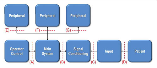
Figure 1: A block diagram of a general medical device, which indicates the location of the interface where isolation can be implemented.
Medical safety standards allow two types of isolation: patient protection (MOPP) and operator protection (MOOP). MOPP complies with IEC 60601 regulations, while MOOP complies with less stringent regulations, such as IEC 60950. In the above example, the system can be classified as requiring interface B to pass IEC 60601 certification, while interfaces A, E, F, and G may only require IEC 60950 certification.
In order to ensure the highest level of safety in some medical systems, all interfaces are required to comply with IEC 60601, because these systems may allow patients to access peripheral devices. In addition, the part of the system that is connected to the patient may be regarded as a peripheral device that will be connected to any of the E, F, and G interfaces shown in the figure. IEC 60601 also specifies the safety when using high-voltage defibrillators. As long as any equipment connected to the patient is not certified to IEC 60601, it must be removed during defibrillation, regardless of whether there is time to do so.
The adoption of USB
The internal interfaces of the system, such as points A, B, and C in Figure 1, are usually UART, SPI, and I2C, depending on cost, performance, and size requirements. The system architect also chooses external connection ports based on interoperability. In the past, PC systems relied on RS-232 serial communication. However, RS-232 is becoming fewer and fewer on PCs, especially notebooks, and the number of peripherals with RS-232 is also rapidly decreasing.
In contrast, USB has grown rapidly, partly because of the rapid popularity of the USB interface and the support of a large number of peripherals. The plug-and-play nature of USB also reduces development costs and the need for special software. In medical equipment, the use of USB is not limited to professionally trained operators, patients can also use USB devices at home to download data to USB storage, and then take it to the hospital for doctors to use. USB can also be used to connect sensors or other measuring devices to the host system. One of the advantages of USB is that it allows up to 127 devices to work on a bus, so even if there is only one USB port, multiple peripherals can be used. In contrast, the RS-232 serial communication port can only handle one device.
USB isolation
In short, USB has some obvious advantages over RS-232, including: expandable to 127 peripherals; plug-and-play operation; hot-swap capability; high data rate (1.5Mbps, 12Mbps, and 480Mbps); industrial compatibility Standard; widely popularized on PC.
Despite these advantages, the popularity of USB in medical systems is not as fast as in other consumer applications. The difference between the medical field and other fields lies in the isolation requirements. Although USB has many advantages over RS-232, the facts show that isolating a USB interface is not as simple as isolating other interfaces.
USB is difficult to isolate because it is a differential, bidirectional interface and requires configuration (via pull-up and pull-down) resistors to indicate bus speed. The two-way feature alone is very challenging, because a certain method must be used to determine the direction of data transfer. In an isolated USB interface, this information must be able to cross the isolation barrier. The control flow is determined by the data structure, not the control signal.
The USB interface consists of 4 wires: VDD, D +, D–, and VSS.
VDD is a 5V power supply, VSS is a reference ground, and D + and D- are differential signals. To make things more complicated, D + and D- can also be used to send single-ended data and can be used to determine the bus status. The pull-up and pull-down resistors on the peripheral side of the bus are used to set the speed and idle state of the USB interface. By definition, data can be transmitted at one of the following three rates: 1.5Mbps (low speed), 12Mbps (full speed), 480Mbps (high speed).
The USB 2.0 standard supports all three data rates (USB 1.1 only supports low-speed and full-speed data rates). It is worth noting that a device can be called a USB 2.0 compatible device even if it does not support 480Mbps.
Because standard optocouplers are inherently unidirectional devices, the isolation interface using optocouplers or other unidirectional isolators must first convert the USB signal into a set of unidirectional signals, as shown in Figure 2 (EEPROMs are not shown in the figure, but it It is often used to store codes for signal conversion). In this example, the D + / D- line from the microcontroller is converted into a single-ended, unidirectional SPI signal. These signals are isolated and then converted back to USB signals using a USB serial interface engine or USB controller. This controller adds multiple components and increases the number of traces, instead of a simple two-wire bus. This method is not only expensive, takes up considerable board area, and requires additional design time, in part because the microcontroller requires software configuration. The complexity of this implementation is the main reason for the slow adoption of USB by medical system architects.
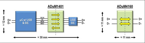
Figure 2: Alternative ways to isolate the USB interface. The figure on the left shows the configuration method of using microcontroller and serial interface engine to convert D + / D- signals into unidirectional single-ended SPI. The picture on the right is a simpler method. The ADuM4160 USB isolator can be inserted into the D + / D- signal path without the need for additional signal conversion components.
Single package USB isolation
A simpler and more cost-effective method of USB isolation is to use a dedicated USB isolator, which can be inserted directly into the D + / D- USB signal path. Such isolation technology now exists, can provide up to 5kV rms enhanced isolation, and supports low and full speed data rates.
Unlike optocouplers, optocouplers use LEDs and phototransistors to send data through isolation barriers through optical transmission, while isolators based on newer technologies use planar transformers to send data through a 20 μm thick polyimide insulation layer. This insulation The layer can withstand 6kV rms voltage. Data transmission is accomplished by induction from one coil to another. Figure 3 shows the structure of this transformer. Figure 4 illustrates how the rising and falling edges of the data stream are encoded as two or a single 1ns pulse, respectively. These pulses are decoded on the receiver side to restore the transmitted data.
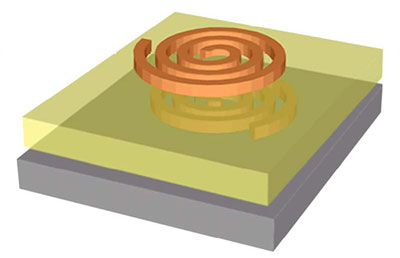
Figure 3: Schematic diagram of a planar transformer. The coil is isolated by a 20 μm thick polyimide insulation layer. The insulation rating of this insulation layer can be as high as 6 kV rms for 1 minute.
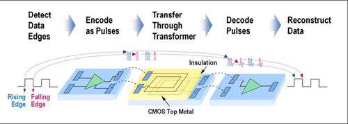
Figure 4: How to send data through the partition. The rising and falling edges are encoded as two and single pulses, respectively. The receiver reproduces the data stream on the other side of the spacer by decoding these pulses. The refresh circuit continuously retransmits data every 1ms to ensure the correctness of the DC voltage.
Compared to optocouplers, using a dedicated USB isolator in a single package has many benefits. The use of transformers allows data to be transmitted bidirectionally through the isolator. Although this technology uses a dedicated transformer to send and receive signals, all coils are the same and contained in a single package. This method cannot be achieved with optocouplers. Similar settings using optocouplers require separate devices to handle communication in each direction.
The speed of the transformer is inherently faster than the LED-phototransistor combination used in the optocoupler, thus allowing the isolator to support the faster data rate and shorter propagation delay required by USB. At the same time, the power consumption of this isolator is low, which can meet the strict standby power consumption requirements of USB.
The most critical advantage of this isolation technology is the ability to integrate additional functions in the isolator product. The space saving effect brought by this integration is shown in Figure 2. Compared with the multi-IC configuration with USB transceiver and optocoupler, the circuit board area occupied by the USB isolator can be reduced by 75%.
With the help of this USB isolation technology, which is more cost-effective and easy to implement, medical devices can take full advantage of USB. For example, in the medical system, the isolated USB port on the home patient monitor can realize the real-time connection between the patient at home and the hospital doctor, thereby providing better and more accurate health care. With an isolated USB, this home patient monitor can be connected to a PC and then transmit data to the hospital in real time via the Internet. As long as it passes the IEC 60601 medical grade safety certification, the system with isolated USB can even maintain the connection with the patient during the shock defibrillation process.
Summary of this article
The widespread use of USB has challenged medical system architects who want to take full advantage of USB. Isolating the USB in these systems is quite difficult and expensive, and it must not detract from the functional enhancements and ultimate cost-effectiveness of using USB. Fortunately, new USB isolators have been developed to solve this problem. This technology can directly isolate differential, bidirectional D + / D-USB signal lines.
it is a two-color CCT temperature led strip. that can be changed color by an external specific controller.
on one strip has two color temperatures, which can meet different color temperature and scene requirements of the customer at the same time.
The led belt surface is lighter and more beautiful than the previous products,Suitable for home decoration lights,(Stairs, door frames, bar counters, wine cabinets, wardrobes, TV cabinets, DIY home decor...
it is more advantageous in the market.
Dimming LED Strip,LED Strip Dimmer,Dimmable LED Strip,LED Strip Light Dimmer
SHEN ZHEN SEL LIGHTING CO.,LTD , https://www.sel-lighting.com