1 Introduction
At present, industrial robot joints are mainly controlled by AC servo systems. In this study, the SIEMENS S-200 programmable controller with mature technology, convenient programming, high reliability and small size is applied to a controllable circulating current reversible modulation system. Robot joint DC servo system is used for servo control of industrial robot joints.
2 Industrial robot joint DC servo system
The industrial robot joint is driven by a DC servo motor, and the positive and negative rotation of the motor is controlled by a circulating current reversible speed regulation system to achieve the purpose of servo control of the industrial robot joint.
2.1 Control system structure
The system adopts SIEMEN S7-200 type PLC, plus D / A digital-to-analog conversion module, which converts PLC digital signals into analog signals, through the BT-I converter speed control system (mainly by the speed regulator ASR, current regulator ACR, circulating current The regulator ARR, the positive group trigger GTD, the negative group trigger GTS, and the current feedback device TCV) drive the DC motor to drive, and drive the robot joints to act according to the control requirements. The system structure is shown in Figure 1.
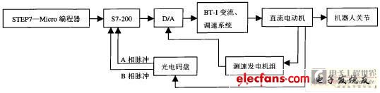
Figure 1 Schematic diagram of the robot joint DC servo system
2.2 Working principle of the system
The principle of the system is shown in Figure 2. The main circuit of the controllable circulating current reversible speed control system adopts a cross-connection method. One secondary winding of the rectifier transformer is connected to Y type, the other is connected to △ type, and the phases of the two AC power sources are staggered by 30. °, the frequency of its circulating current is l2 times the power frequency. In order to suppress the AC circulating current, two equalizing reactors are connected between the two groups of controllable rectifier bridges, and one smooth wave reactor is still retained in the armature circuit.
The control circuit is mainly composed of speed regulator ASR, current regulator ACR, circulating current regulator ARR, positive group trigger GTD, negative group trigger GTS, and current feedback TCV (see Figure 2), of which 2 groups of triggers have synchronization signals Respectively taken from the synchronous transformer corresponding to the rectifier transformer.
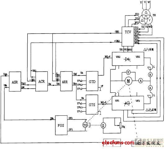
Figure 2 Schematic diagram of the industrial robot joint DC servo system
When the system is set to zero, the speed regulator ASR and current regulator ACR are locked to zero by the zero speed blocking signal. At this time, the system is mainly composed of a cross-flow regulator ARR cross feedback constant current system. Due to the influence of the given circulating current, the two sets of thyristors are in rectified state, the output voltage is equal and the polarity is opposite, the DC motor armature voltage is zero, the motor stops, and the output current flows through the two sets of thyristors to form a circulating current . The circulating current should not be too large, generally limited to about 5% of the rated current of the motor. When starting in the forward direction, as the speed signal Ugn increases, the blocking signal is lifted, the speed regulator ASR outputs positive, and the motor runs in the forward direction. At this time, the positive group current feedback voltage + Ufi2 reflects the sum of the motor armature current and the circulating current; the negative group current feedback voltage -Uril reflects the armature current, so the main current can be adjusted. However, the given current signal -Ugih and the cross current feedback signal -Ufil added to the input of the positive group current regulator have little effect on this adjustment process. The input voltage of the anti-group circulating current regulator is (+ Uk) + (-Ugih) + (Ufi2). With the continuous increase of the armature current, when it reaches a certain level, the circulating current automatically disappears, and the anti-group thyristor enters the standby Inverted state. The situation is reversed when starting in reverse. In addition, the controllable circulating current reversible speed control system still has the process of inverting the bridge, reverse connection braking and feedback braking. Since the start-up process is also a process in which the circulating current gradually decreases, the system's circulating current reaches its maximum value when the motor stops. Circulation helps the system to cross the switching dead zone and improve the transition characteristics.
3 System programming
The program design scheme is to manually input an angle value to let the motor rotate, and detect the rotation angle of the motor through the photoelectric code wheel connected to the motor, and turn the rotation angle into a pulse signal. Because the speed of the motor is very fast, the pulse signal can only be sent to the high-speed counter of the PLC. Then compare the pulse record of the counter with the input of the hand. If they are equal, it means that the motor has reached the specified angular position, otherwise, continue to make corrections. It is worth noting that, since the motor will have a certain inertia from sudden rotation to stop, there should be a certain error when comparing the signals, otherwise the motor will always be in the corrected position. The system program block diagram is shown in Figure 3.
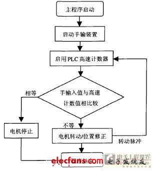
Figure 3 System program block diagram
4 Conclusion
Based on the DC servo system developed by PLC, taking advantage of the PLC's strong expansion capability, a manual transmission device is added to realize the visual operation of the industrial robot joint DC servo system.
Automatic Coffee Machine,Coffee Machine,Cappuccino Maker,Single Serve Coffee Maker,Drip coffee maker,POD coffee maker,Espresso coffee maker
FOSHAN FORTUNE ELECTRICAL APPLIANCE CO.,LTD , https://www.coffelady.com