introduction
Since the emergence of digital signals, with its unparalleled advantages, it has quickly broken the dominance of the original analog signals. With the development of audio processing technology, audio processing algorithms are becoming more and more complex. It is not only difficult and costly to implement these algorithms using traditional analog signal processing methods, and some of them are even impossible to implement. However, due to the increasing speed of digital signal processors (DSPs), these complex audio processing algorithms can be easily implemented with DSPs, so many audio processing is now implemented with DSPs. However, the original audio signals are all analog. If digital signal processing technology is used for audio processing, the first problem to be dealt with is audio collection, processing and output system.
This article introduces an audio processing system with 8 analog audio inputs, 8 analog audio outputs, 1 digital signal input, and 1 digital signal output. Analyze the hardware connection and function realization method of the system, and the software working principle of the system.
1 Design plan
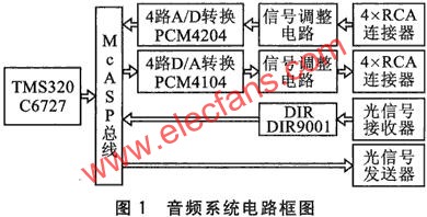
The system design framework is shown in Figure 1. The digital signal processor uses TI's 32-bit floating point DSPs TMS320C6727, the A / D conversion part uses 2 TI's audio analog / digital conversion chips PCM4204, and the D / A conversion part uses 2 TI's audio digital / analog conversion The chip PCM4104, the digital signal receiving part selects the Digital Audio receiving interface chip DIR9001.
PCM4204 and PCM4104 are 4-channel, 24-bit, 216kHz sampling frequency analog / digital and digital / analog chips, respectively. PCM4.204 supports data transmission formats such as left parity, right parity, and I2S, and the master / slave mode can be set; PCM4104 supports data transmission formats such as left parity, right parity, I2S, and soft mute mode , Soft / hard two control methods are available.
DIR9001 is used to receive bi-phase coded signals with a sampling frequency between 24 and 108 kHz. The output format is I2S, left check, right check, etc.
2 Hardware circuit
The Audio System hardware circuit is divided into three parts: audio acquisition, audio playback and communication. The audio acquisition part realizes the conversion of analog audio signals into digital audio signals and transfers them into TMS320C6727; the audio playback part realizes the output of digital audio signals from TMS320C6727 and converts them into analog audio signals to drive the speakers; the communication part realizes the data transmission with other audio equipment. The collection, transmission and communication of audio data are completed through the McASP port of TMS320C6727. TMS320C6727 has 3 McASP ports: McASP0, McASPl, McASP2 ports. Among them, McASP0 port has 16 serial data ports AXR0 ~ AXR15, McASPl has 6 serial data ports (shared AXR8 ~ AXRl3), and McASP2 has 2 serial data ports (shared AXRl4, AXRl5). Audio collection and playback use McASPO's AXR0 ~ AXR7, audio data communication transmission using McASP0's AXRl4, receiving using McASP2 port.
The clocks of PCM4204 and PCM4104 are generated by the clock circuit composed of PLL1707, and the clock frequency is 24.576 MHz (256fs, fs is the sampling frequency). The receiving data clock and transmitting data clock of each McASP port are independent of each other, and each has its own main clock (AHCLK). When the McASP interface provides a clock signal for I2S, BCK and LRCK can be obtained in addition to the system clock. Obtained from AHCLK frequency division.
2. 1 audio collecting circuit
The connection diagram of the audio acquisition circuit is given in Figure 2. Because the focus of this article is not on the front-end conditioning circuit, the figure only shows the hardware connection between the PCM4204 and the MeASP0 port of the TMS320C6727.

The data transmission format between PCM4204 and McASPO port uses I2S bus. I2S bus has three main signals: bit clock (BCK), frame clock (LRCK) and serial data.
PCM4204 has two working modes: Master / Slave: When working in Master mode, PCM4204 generates BCK signal and LRCK signal; When working in Slave mode, PCM4204 receives BCK signal and LRCK signal. McASP interface of TMS320C6727 can also receive BCK signal and LRCK signal. Considering that the BCK signal and LRCK signal of the McASP interface are obtained by dividing the internal clock of the DSPs, the precise clock signal required for audio cannot be obtained, so the BCK signal and LRCK signal are generated by the PCM4204. In order to prevent two pieces of PCM4204 from being set to Master mode at the same time and causing clock signal confusion, set one of them to Master mode and the other to Slave mode. PCM4204 working in Master mode provides BCK signal and LRCK signal for the receiving clock of McASP0 port and another PCM4204 at the same time.
The AXR0 ~ AXR3 of McASP0 port are set to receive mode and are connected to the signal output ends of two PCM4204 respectively, and are used to receive the serial digital audio signal sent from PCM4204.
2.2 Audio playback circuit
The audio playback circuit completes the conversion and playback of digital signals to analog signals. The connection diagram of the audio playback part is shown in Figure 3.

PCM4104 can only work in Slave mode, so the clock signal should be provided by AFSX0 and ACLKX0 of McASP port. In order to ensure that the sampling frequency of audio playback is the same as the sampling frequency of audio collection, the clock signals provided by AFSX0 and ACLKX0 are obtained from the frequency division of AHCLKX0, and the clock signal of 24.576 MHz is provided by the clock circuit of AH-CLKXO. Similarly, the system clock of PCM4104 is also provided by the clock circuit.
AXR4 ~ AXR7 of McASP0 port are set to send mode and connected with the signal input pin of PCM4104 to realize the playback of serial digital audio signals.
2. 3 audio communication circuits
The audio communication circuit can realize the data transmission between the audio system and other devices. The transmission format is S / PDIF, using Biphase Mark Code (BMC). The McASP interface supports this transmission method and can be output directly from the McASP port. For signal reception, the BMC signal is converted into I2S format through the digital audio demodulation chip DIR900l and transmitted to the receiving end of the McASP2 port. The hardware connection is shown in Figure 4. McASP2 is used as the receiver to receive the digital audio signal demodulated by DIR9001. The AXR15 port of MeASP2 is set as the output port, and the audio data is output in the BMC format.

3 Audio system hardware configuration
3.1 PCM4204 settings
The control pin of PCM4204 is used to set its working mode. Pin S / M is used to select the master / slave mode, FSO, FS1, and FS2 are used to select the sampling mode, and FMTO, FMT1, and FMT2 are used to select the audio data format. The pin configuration of 2 PCM4204 is as follows:

PCM4204 has 3 working modes: Single Rate, Dual Rate and Quad Rate. According to the above configuration information, the PCM4204 sampling mode is set to Dual Rate mode; the sampling frequency fs is 1/256 of the system clock, which is 96 kHz; the data output format is I2S.
3.2 Configuration of PCM41 04
PCM4104 is divided into software configuration and hardware configuration, this design uses hardware configuration. Among them pins FSO, FSl are used to configure the sampling mode; FMTO, FMTl, FMT2 are used to select the format of receiving digital audio signals; DEM0, DEMl are used to select de-emphasis. The configuration is as follows:

PCM4104 also has 3 working modes: Single Rate, Dual Rate and Quad Rate. According to the above configuration, PCM4104 is configured as DualRate data receiving mode; the data receiving format is I2S; there is no de-emphasis.
4 System software design
The system software is written in C language under the TI company's DSP integrated development environment CCS3.3, and its software flow is shown in Figure 5.

The initialization procedure includes the clocks, interrupts, McASP port configuration of DSPs TMS320C6727, and the configuration of PCM4204 and PCM4104. After the initialization is finished, PCM4204 starts sampling, and the data is transferred to the receiving buffer registers RBUF [O] ~ RBUF [3] of McASP0 port. If a digital signal comes in, it is also transferred to the receive buffer register RBUF [14] of McASP0 port.
The data processing program can perform processing such as filtering, noise reduction, audio encoding, and data compression on the sampled audio data or digital audio data from other devices.
The audio playback program can realize the data transmission from the data in the DSP to the D / A chip, and the digital signal sending program is used to convert the data in the DSPs into a BMC format signal and pass it to the coaxial cable connector.
in conclusion
The 8-channel audio acquisition, processing, and playback system designed by the author can achieve high signal-to-noise ratio audio acquisition and playback. In the actual test process, the collected audio signal was directly played back without processing. The sound effect was very good, and the sound distortion and delay were not felt, and the communication in the digital audio signal loopback mode was successfully achieved.
Powered Subwoofer,Aluminum Cone Woofer,Indoor Active Subwoofer,Home Theater Subwoofer
The ASI Audio Technology Co., Ltd , https://www.asi-sound.com