At present, 90% of welding robots in service work in the "teaching reproduction" mode, and a few work in trajectory planning. During the welding process, there will be certain errors in the welding torch and the center of the welding seam, and the welding process is a complex, non-linear, and many interfering factors, such as thermal deformation, undercutting, wrong side of the welding workpiece, and changes in the welding seam gap, etc. It is unpredictable, these factors will directly affect the welding quality. Based on the application of "teaching reproduction" or trajectory planning, real-time weld seam correction can further improve the welding accuracy, and is especially suitable for the production of workpieces that are difficult to be controlled by automatic welding in auxiliary engineering such as welding deformation and complicated assembly. In this paper, based on the butt welding of the new spacecraft fuel tank LF6 aluminum alloy 2 mm thin plate, for the pulse tungsten inert gas shielded welding (GT AW) welding method, the flat seam and flat flange welding seam tracking test, The traditional "teaching reproduction" robot was developed into an arc welding robot system with real-time welding seam tracking.
1 Experimental part
1. 1 test system composition
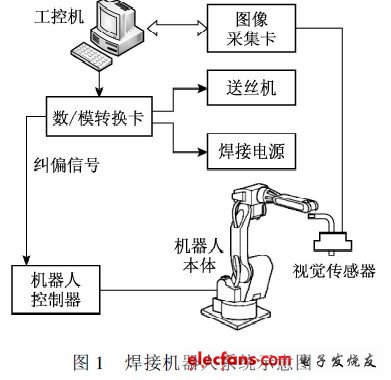
In this experiment, the execution mechanism includes HP6 welding robot of Yaskawa Electric Co., Japan, two-axis flipping positioner, single-axis head-tail positioner, IN VERTERELESON 500P AC-DC dual-purpose GT AW produced by Japan OTC company. Welding power supply, CM-271 wire feeder and HC-71 wire feed control box. The control system is Advantech's industrial control computer, and the sensing system is the self-developed CCD passive light vision system and image acquisition card. The entire system is shown in Figure 1.
Considering the weldability of the LF6 aluminum alloy thin plate, AC pulse welding is used for welding, with a pulse frequency of 2 Hz, a base current of 50 A, a peak current of 125 A, and a welding speed of 2.6 mm / s.
1. 2 image acquisition and processing
1. 2. 1 Open small window analysis
A “small window†is used to obtain the weld feature information. A small window of 100 frames × 120 frames is opened in the weld area, and only the image in this window is processed. This window contains the feature information required for welding seam tracking, and also reduces a lot of unnecessary image information. The CCD camera and the wire feed nozzle are fixed on the welding torch, that is, the relative positions of the welding torch, tungsten electrode, and wire feed nozzle on the image plane projection are unchanged, and the axis of the CCD camera, the axis of the welding gun and The welding seam is adjusted to the same plane. In this way, the projection of the axis of the welding gun on the image plane is a horizontal line, which provides convenient conditions for subsequent tracking.
1. 2. 2 Image processing algorithm
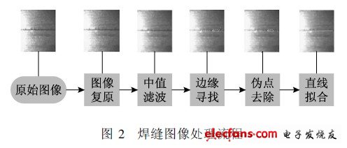
In the experiment, first extract the upper and lower edges of the weld, and after removing the pseudo points, perform the least squares fitting to obtain the center line of the weld. The image processing algorithm flow mainly includes image restoration, median filtering, edge search, pseudo point removal and least squares fitting, as shown in Figure 2.
The inverse filter method is used for image restoration, and the 3x3 template median filter is used at the same time. The gray value of the current pixel is obtained from the intermediate value of the pixel gray value of its 8 neighborhoods.
After observing and analyzing the image, it is found that the edge of the weld seam changes greatly in gray level compared with other areas. Therefore, the edge point of the weld is determined according to the rate of change of the gray value, that is, the two points with the largest rate change in each column are taken as the upper and lower edge points of the weld. The use of this edge detection algorithm is based on the characteristics of the 2 mm thin plate. The lack of grooves makes the large gray change at the weld seam easy to capture in the entire image, and the small amount of calculation of this algorithm will not affect Real-time image processing.
After the above image processing, the weld edge cannot be accurately obtained. There are still false edges. How to remove the false edge points and identify the real weld edge is the most difficult and the most critical technology in image processing. The pseudo-edge points are removed by scanning the neighborhood 24 from the top and bottom directions to the middle progressively. Since the edge of the weld is continuously changing, it is assumed that there is an image processing error within 2 pixels. If there is no adjacent feature point in the vicinity of a certain feature point 24, the point is considered to be a false edge point or an isolated point.
Qunsuo aims at providing our customers high qualified Industrial Rugged Pda. In order to meet customers using environment, our PDAs all pass IP65 certification. With the stable quality of our Handheld Android Pda, we gain many reliable customers, help many customers provide IT solutions. If you are also looking for reliable PDA manufacturer partner, Qunsuo will be your good choice. Welcome to contact us for more details!

Industrial Rugged Pda
Android Pda Europe,Pda With Desktop Charger,Rugged Handheld Pda Honeywell,Handheld Barcode Scanner Pda
Shenzhen Qunsuo Technology Co., Ltd , https://www.qsprinter.com