GPS is the abbreviation of Global PosiTIoning System (Global Positioning System) in English, while its Chinese abbreviation is "ball position system". The space part of GPS is composed of 24 working satellites, which is located above 20200km from the surface, and is evenly distributed on 6 orbital planes (4 per orbital plane), with an orbital inclination of 55 °. In addition, there are 3 active backup satellites in orbit.
GPS module
The design uses u-blox's GPS receiver module nr-86, which is small in size and light in weight, and integrates the NemeriX chip solution with high sensitivity and low power consumption in the design. This module can quickly locate, 1Hz navigation update frequency, and can track 16 satellites simultaneously. Support WGS-84 data protocol. It has a simple interface. The TTL level serial port outputs NMEA-0183 format data. It only needs to connect the TX end of the module to the RX end of the 51 single chip microcomputer, and the single chip P1.0 is connected to the RESET end of the module to control the module reset. This design uses the $ GPRMC protocol in the NMEA default format, because the protocol is streamlined, the information coverage is wide, and the data is easily collected and processed by the single-chip microcomputer.
Modulation and demodulation chip MSM6882
During design, the 89S52 MCU is connected to the chip through a synchronous serial port, and then the chip modulates the signal to an analog channel, and then loads the signal onto a walkie-talkie (PTT), which realizes wireless transmission. The input clock period of the CLK pin of the single-chip microcomputer should be in the range of 0.42μs to 1.35μs, and the amplitude of the modulation signal input to the radio station can be adjusted by an adjustable resistor. The signal is sent to the AI ​​pin of MSM6882 after the signal is limited, and the other is sent after amplification, detection, and amplitude comparison.
Into the microcontroller, as the carrier detection signal. When the system detects the signal, it can use delayed transmission to avoid co-channel interference and channel blocking.
Speech synthesis chip XF1M01
The speech synthesis chip XF1M01 receives the text to be synthesized through the asynchronous serial port. It contains the GB-2312 Chinese character library and an external single transistor to drive the speaker, which can realize the conversion of text to sound (TTS). The audio output in the design is sent to the amplifier. Loudspeaker to get a larger volume and adapt to outdoor environment. Just give it the internal code of Chinese characters (that is, 16-bit binary characters), you can read a word, send more and read more, so the storage space requirements are low, suitable for the application of electronic patrol system. When the chip is idle, the Ready terminal outputs a low level, so connect it to the single chip P3.2, the single chip can scan the pin, and when the chip is idle, it sends data to it through the asynchronous serial port. The transmission baud rate is determined by the two pins Baud_0 and Baud_1. 9600bps is used in the design. The P1.1 of the one-chip computer is connected with the RESET end of the chip to control the chip reset.
In the past, security inspections did not have much equipment. Each person had a walkie-talkie and a baton. With the advent of GPS, it becomes possible for the base station, the central station, to grasp the geographic location information of each security guard. That is, each security guard is equipped with a set of GPS positioning equipment, and a set of wireless transceiver equipment that sends its position information to the main station. Because it is costly to re-equip each security guard with a set of equipment, and it is not realistic to eliminate the existing intercom, so using the intercom as an existing channel carrier will do two things. It is convenient and practical to build an unprecedented security system.

Figure 1 Application of electronic inspection system
The combination of the motherboard and various functional modules constitutes a mobile intelligent terminal. It includes MCU namely single chip AT89S52, GPS receiving module, analog modulation and demodulation chip MSM6882, liquid crystal display module LCD1602, speech synthesis chip XF1M01, see Figure 2.
The mobile intelligent terminal completes the forward GPS data collection, processing and transmission, and reversely receives, recognizes and executes the command of the main station.
The GPS module outputs GPS information once per second, and the MCU collects it, and displays its own latitude, longitude, time and date on the display module. Then load the data to the intercom through the modem chip and then wirelessly transmit it to the main station to complete the forward task.
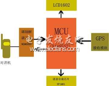
Figure 2 Smart terminal structure
Then there will be about half a second of time waiting for the command of the main station. If the command of the main station is received, the command type is judged according to the data frame, the corresponding data is extracted, and the corresponding display operation and voice prompt operation are performed after the MCU processing to complete the reverse To task.
When the terminal receives the target command information and executes the processing, the preamble is changed when it is retransmitted back to the main station to indicate that the command is received successfully, so that the main station makes corresponding processing. For example, the preamble can be changed from "start" to "start1".
Compared with the previous portable devices with single functions and lack of user-friendly interface, this GPS data collection, processing, and transmission integrated intelligent terminal has expanded functions. First of all, each security guard can see his latitude, longitude, time and date on the LCD screen, giving the security guard an intuitive and clear sense of geographic location. In addition, you can receive the command information from the main station in real time, and after processing by the MCU, compare the latitude and longitude of the place where the main station dispatches to the LCD screen and compare it with your own position to realize the transparency of the information. Another improvement is the intelligent voice prompt and the calculation of the angle offset. By receiving the latitude and longitude of the target dispatch location sent by the main station and comparing it with its own position, it clearly and clearly indicates how far the security guard should go. The system terminal adopts 51 series single chip microcomputer as MCU. Use the modem chip to load the signal to the intercom to achieve wireless transmission instead of an independent wireless communication module. The LCD screen selects the simple and easy-to-use LCD1602. The solution greatly reduces costs and is stable and reliable.
The system must formulate a reasonable flow (Figure 3) in order to give full play to the MCU's functions of data acquisition, processing and transmission.
In order to make the system work as stable as possible, as many functions as possible (upstream and downstream have their own processing execution time), and data update as fast as possible (GPS data one frame per second, the system processing is not enough, you can change it to two seconds a Frame), the system must formulate a reasonable timing in order to allocate time uniformly.
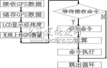
Figure 3 terminal workflow
FBT Splitter fiber optic components adopt unique materials and manufacturing process, can precisely control fiber fusion encapsulation, to ensure low insertion loss, wavelength related loss and polarization dependent loss.
Molten pull cone can depend on different fiber optic components, operating wavelength range than spectrophotometer, connector type and the flexible configuration, encapsulation can be rapidly applied in all kinds of product design and project plan.
The FBT splitter has many years of technology and experience, the one window splitter is fixed using a wavelength connecting device, commonly used as 1310nm, 1490nm or 1550nm. We can provide 1XN or 2XN configuration, Coupling Ratio is optional.
Optical Splitter,Coupler Splitter,One Window FBT Splitter,Single Mode Fiber Splitter
Chengdu Xinruixin Optical Communication Technology Co.,Ltd , https://www.xrxoptic.com