introduction
The shipboard antenna stabilization platform is to provide a microwave antenna mounted on the mast of the ship with an installation level that is not affected by the ship's sway. Its function is to compensate the vertical and horizontal sway angles caused by the movement of the ship under the sway of the ship, so that the antenna Always perpendicular to the horizontal plane. However, because its installation location is in a harsh electromagnetic interference environment, in addition to the radiation of the microwave antenna carried by itself, there is also radiation interference of various types of radar and communication antennas nearby, and the PWM interference of the internal motor to ensure that the equipment is in a bad electromagnetic environment. To work properly in an interference environment, electromagnetic compatibility must be strictly designed. Electromagnetic interference (EMI) is the electrical noise generated by electronic equipment or electrical equipment. These electrical noises appear in many forms and can be continuous, random, or periodic. The formation of EMI must have three factors at the same time: the source of electromagnetic interference; the receiving equipment sensitive to the interference energy; and the propagation path that transmits the interference energy from the interference source to the receiving equipment. If a system is neither an interference source nor a receiving device, then the system is electromagnetically compatible.
The study of electromagnetic compatibility is carried out around the three factors that constitute electromagnetic interference: improving anti-interference performance and reducing interference radiation and interference conduction to other equipment. Appropriate system design techniques can suppress emission conduction and radiated interference. Appropriate design techniques can harden the system to reduce its sensitivity to interference. Appropriate shielding, grounding, and filtering can cut off the propagation path of interference to protect the victim equipment. 1 The sensitivity of the power line spike signal sensing design The sensitivity of the device to the spike signal means that the device can withstand the specified level of transient interference without failure or chaos in the working state. The test condition for the sensitivity of the power line spike signal (CS106) is to inject a spike signal with a pulse width of less than 5μs and an amplitude of 400 V on the ungrounded AC power line. The CS106 test schematic is shown in Figure 1.
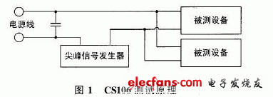
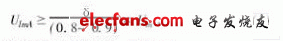
During the test, the spike signal is synchronized with the peak value of the AC signal waveform. At the same time, in order to generate the maximum following energy, the spike signal is applied to the zero crossing point, that is, the phase angle of 0 degrees, 90 degrees, 180 degrees, and 270 degrees are tested. The output voltage of the spike signal generator gradually increases from 0V. When the output voltage increases to 350 V, the LCD screen of the device appears white, and the device is interfered by the spike signal and cannot work normally. 1.1 Non-linear device transient suppression Whether it is from the power line or from the signal line into the transient, you can use nonlinear device attenuation. These devices are connected in parallel with the protected circuit. For normal signal or voltage levels, it appears as a high-impedance state—mainly determined by its own capacitance and leakage characteristics. When the voltage of the interference source is greater than its breakdown voltage, the device will immediately change to a low resistance state, so that the current from the transient source leaves the protection circuit, limiting the transient voltage on the protection circuit. Taking the transient voltage absorption diode (TVS) as an example, TVS is a silicon avalanche diode, which is small in size and short in response time. Before breakdown, the TVS appears as a high-impedance load across the line input, and when a transient high voltage occurs, it is activated, the PN junction has an avalanche effect, and absorbs a lot of energy, so the clamping method limits the line voltage to allow Within range. When selecting these nonlinear devices, they must be able to withstand the continuous operating voltage of the circuit and have a safety margin to absorb energy from any expected transient. The typical installation location diagram of the transient suppressor is shown in Figure 2 (omitted). The design of this system uses varistor and transient voltage absorption diode for electromagnetic compatibility design. A varistor is connected in parallel between the power supply line of the controller of the antenna stabilization platform. The varistor has a certain capacity to withstand the surge current and voltage. Generally, the nominal voltage is selected according to formula (1):
In the formula, Um is the peak value of the rated voltage of the line, which is the rate of voltage increase. Generally, it is 1.05 ~ 1.10. In the design of the inclinometer and gyro signal transmission circuit, TVS is connected in parallel at both ends of the power tube; meanwhile, in parallel at both ends of the DC power supply TVS, TVS is connected in parallel between the signal line and the ground of the CAN bus, and they all play a role in protecting the circuit and resisting electromagnetic interference. 1.2 Crosstalk effect inside the cable The layout of the cable routing inside the control system has a great influence on the coupling of the local electric and magnetic fields between the cables. In order to minimize the coupling between cables, different types of cables should be zoned and kept at least 150 mm apart; when different types of cables cannot avoid adjacent traces, try to shorten the length of the traces . This can reduce the crosstalk effect inside the cable and achieve better results for the system's electromagnetic compatibility design. 2 Electric field radiation sensitivity (RS103) design antenna stabilization platform In order to ensure that the antenna is always perpendicular to the horizontal plane and is not affected by the ship's sway, an inclinometer and rate gyro are used to measure the ship's inclination signal and sway rate signal to introduce feedback and feedforward, respectively Form a composite control strategy to realize the servo control of the antenna stable platform. In this system, the force-balanced inclinometer LCF100 was used to measure the inclination signal of the ship, and the antenna stable platform was placed in an environment of 10 kHz to 40 GHz and a radiated electric field strength of 200 V / m. Interference, the system cannot work normally. 2.1 Using shielding technology to reduce electric field radiation shielding is a kind of shielding body made of conductive or magnetically conductive materials made of shells, plates, sleeves, cylinders and other shapes, which is an effective measure to limit electromagnetic energy within a certain space and suppress radiation interference. The shielding body is used to isolate the external electric field from the shielding space, and at the same time, the shielding body is grounded to eliminate the influence of electric potential and achieve effective shielding. Because the mechanism of shielding is electric field reflection loss, and secondary reflection tends to reduce the overall reflection loss, the higher the coating resistivity, the worse the shielding effect. In the design of the electric field shielding, a good conductor should be used to make the shielding body, which can attenuate the electromagnetic energy and reduce the radiation interference through the reflection and absorption of electromagnetic waves. The hole of the shield is inevitable in practical applications, it is an important factor affecting the shield. In order to ensure the shielding effect, reduce the resistance of the shielding body, and when designing the shielding body, the hole size perpendicular to the direction of the electric field should be minimized. In this system, a shielding box made of silver plated on the surface of the aluminum shell is used for electric field shielding. The inclinometer and signal conditioning circuit are placed in this shielding box.At the same time, 2 layers of shielding are used to control the distance between the 2 layers as close to 1/4 wavelength as possible. Odd number of times (because when the frequency is very high, the electromagnetic wave will produce resonance between the two shielding layers. When the spacing between the two layers is an odd multiple of 1/4 wavelength, the double-layer shielding has the largest screen effect; when the spacing between the two layers is 1 / 4 wavelength even times, the screen effect is the smallest), effectively reducing the impact of electric field radiation on the inclinometer signal.
2.2 Using grounding technology to reduce electric field radiation
When shielding technology is used to reduce electric field radiation, the shield must be grounded to eliminate the influence of electric potential in order to achieve effective shielding. Grounding technology is a very effective measure in electromagnetic compatibility design. There are three basic forms of grounding, single-point grounding and multi-point grounding. These methods can be used alone or in combination. What kind of grounding method should be used depends on the specific situation. But one thing needs to be paid attention to. The length of the ground lead must be less than 1/4 of the operating wavelength λ. This is only considering the minimum requirement of the "ground" effect. The actual length of the ground lead depends on the power source allowed to pass through the ground wire. The magnitude of the voltage drop. If the circuit is sensitive to this voltage drop, the length of the ground lead is not greater than 0.05λ or less; if it is only generally sensitive, the ground lead can be longer, but generally does not exceed 0.15λ. At the same time, in order to reduce the impedance of the ground lead, the end of the ground lead should be lapped on the ground plane in parallel. 2.3 Using filtering technology to reduce electric field radiation
Filtering is the most direct and effective way to suppress conducted interference. At the same time, because good filtering can suppress the interference source, it also has a significant effect on the suppression of radiated interference. The suppression effect of the filter on electromagnetic interference is based on the rational selection of the form and parameters of the filter circuit. In this system design, by designing a Bessel low-pass filter with a cutoff frequency of 2 kHz, the noise signal above 2 kHz is filtered out, thereby suppressing the radiation interference of the radiation source of 10 kHz to 40 GHz.
3 Conducted emission interference (CE101) design of Power Cord
3.1 Test method
The antenna stabilization platform system is composed of a monitoring unit, a drive control unit and a host unit. These three parts are installed in different locations, and the monitoring unit and the drive control unit are connected by a 30 m cable.The output power of the drive control unit is close to 1 kW.In order to realize the remote control of the drive control unit by the monitoring unit, in the drive control unit Use AC zero-cross trigger solid state relay (SSR) for AC switch control. The CE101 test block diagram is shown in Figure 3.
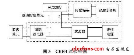
In Fig. 3, the monitoring unit controls the input of the SSR. The control voltage of the monitoring unit to the SSR is DC12V. When DC12V is added to the input of the SSR, the output of the SSR is connected, and the AC220V is connected to the drive control unit and filtered by the filter Then the linear system supplies power to the target system. Pass a live wire at the input of AC220V through the sensing probe, and connect the test end of the sensing probe to the EMI receiver. When the monitoring unit remotely supplies power to the drive control unit, the EMI receiver is tested according to the CE101 standard and the test curve is recorded. The results show that the test curve has sine half-waves at the odd multiples and even multiples of 50 Hz, and at the same time, the waveform has parts beyond the standard curve at even multiples. CE101 item of electromagnetic compatibility test failed.
3.2 Cause analysis
In order to find the cause of electromagnetic interference, we first give a brief introduction to the principle and structure of AC zero-cross trigger SSR [1]. SSR is a new type of non-contact electronic switching device composed of solid-state electronic components. It is generally composed of coupling circuit, zero-crossing circuit, switching device and absorption circuit. SSR is generally a 4-terminal component, of which 2 terminals are input terminals and the other 2 terminals are output terminals. Adding a control signal to the input can control the "on" and "off" of the output to complete the switching function. The coupling circuit uses the photoelectric coupler as the channel between the input and the output, and is completely electrically isolated to prevent the output from interfering with the input. The zero-crossing circuit ensures that the input signal triggers the switching device when the voltage at the two terminals of the switching device is zero-crossing, thus completing the on and off actions under the voltage zero-crossing condition, reducing the interference and pollution generated during the switching process. The absorption circuit is composed of R and C. Its function is to prevent the impact and interference of the peak voltage and surge current on the switching device brought by the power supply. It can be known from the principle of SSR that the input signal of SSR triggers the switching device at the instant when the voltage at the terminal of the switching device 2 crosses zero, thus completing the on and off actions under the condition of voltage zero crossing. The voltage zero-crossing point is not really at 0 V, but within the range of ± 10 ~ ± 25 V, that is, the input signal is always near the AC voltage zero-crossing to trigger the SSR to achieve zero-crossing triggering. Taking a cycle AC220V sine wave as an example, when using solid-state relays, the zero crossing points are at 0Hz, 50Hz, and 100Hz.At this time, the switching device is quickly turned on and off, and the power circuit current change rate di / dt, voltage change The rate du / dt is relatively large, which causes electromagnetic interference.
3.3 Solution
According to the mechanism of electromagnetic interference, PHOTOMOS relay is used instead of AC zero-crossing trigger SSR, and the CE101 electromagnetic compatibility test is carried out according to the above method. The test results only have a sine half-wave at the odd multiple of 50 Hz, and the waveform at the odd-multiple frequency is exactly the same, no more sine half-wave at the even multiple of the frequency, the test curve is within the range of the CE101 standard curve, complete 25 Electromagnetic compatibility design for conducted emission interference of Hz ~ 10 kHz power line.
4 Conclusion
This paper takes the electromagnetic compatibility problems encountered in the project design process as the research object, analyzes the causes of electromagnetic interference and proposes solutions, and has received good results in practical applications.
- Universal fit: compatible with all automobiles, boats and devices equipped with a 12V power source
- CIRCUIT PROTECTION: Power relay-safety protection and conversion circuit. Blade fuse protects the circuit when overcurrent or short circuit occurs.
- ILLUMINATED SWITCH: 3 pin on/off rocker switch with red indicator light when truing on, easy to turn on or off, has been passed test of 5, 000 times pressing.
- TWO AVAILABLE LEADS: With 2 sets of light output connectors for dual lighting fixtures less than 180W, the connection is more stable.
- PACKAGE INCLUDE:1 x Wiring Harness Kit ,1 x Instructions,
-


Light Wire Harness,Light Bar Wiring Harness,Led Light Bar Wiring Harness,Led Light Wiring Harness
Dongguan YAC Electric Co,. LTD. , https://www.yacenter-cn.com