TPMS external coding memory type tire positioning technology design scheme
TPMS technology and tire positioning principle
Automobile tire pressure monitoring system (TPMS) is mainly used for automatic monitoring of tire air pressure in a timely manner when the car is running, and early warning of low tire pressure and high temperature and high tire pressure puncture caused by tire leakage to ensure driving safety. The tire positioning in TPMS refers to the process that the system receives the signal from the tire transmitting module and recognizes and determines which tire.
The problem of tire repositioning
Due to the uneven load of the front, rear, left and right wheels, the steering of the front wheels and the different suspension angles of the front and rear axles, the wear degree and position of each tire are usually different. In order to prolong the service life of the tires and achieve the effect of simultaneous wear of the four tires, this requires regular tire replacement. In the process of tire transposition, the corresponding emission detection module will also transpose. This results in the ID code and the tire identification information originally stored in the receiving and displaying module MCU no longer applicable to the position of the tire after tire change, that is, the correspondence between the tire pressure and temperature information on the display and the tire produces an error. If the new tire is replaced or the emission detection module of a certain tire is damaged, the user needs to replace the module. The ID code of the new module is different from the damaged emission detection module. The relationship between the ID code and the tire identification information originally stored in the MCU of the receiving display module is no longer applicable to the ID code after replacing the module. The receiving display module will discard the information of the replaced module, and the new module will not be displayed on the display. Pressure and temperature information. In this way, there is a problem of tire repositioning when the tires are replaced or replaced.
Tire positioning technology used by existing TPMS
At present, the following four methods are commonly used to solve the problem of repositioning TPMS tires and relocating tires.
1 In the fixed coding type fixed coding method, the ID code in the MCU receiving the display module and the corresponding positioning information of the tire are solidified at the factory and cannot be changed during use. The shortcomings of this method are: installation misalignment will lead to confusion in positioning; after the transmission module is damaged, the user must purchase a module with the same code as the damaged module from the original manufacturer; the transmission detection module must be reinstalled according to its marked position when the tire is replaced.
2 Interface input type The interface input type positioning technology is to print the identification ID code of each transmitting module on the outer packaging or product, but when the tire is transposed or the transmitting module is damaged, the identification ID code must be input to the receiving end with a key re-locate. The identification ID code of the interface input type is 16 or 32 bits, the input process is complicated, and the problem of code group input error is prone to occur. In addition, these buttons are very abrupt on cars with many instruments.
3 Low-frequency wake-up Low-frequency wake-up positioning technology uses the near-field effect of low-frequency (LF) signals (125kHz). In this scheme, there is an LF antenna near each tire; TPMS can send out an LF signal through the LF antenna near the corresponding tire, individually trigger the emission detection module of the corresponding tire, and then the triggered emission detection module will pass the identification code The RF is transmitted, and the receiving module obtains the corresponding ID through the RF signal, thereby automatically determining the tire position. The shortcomings of this positioning method are: four LF antennas are required to be installed near the corresponding tires, and the workload of installation and wiring is large; the LF signal may falsely trigger the adjacent emission detection module; the electromagnetic environment on the car is complicated and there are various Interference will cause interference to low-frequency signals, resulting in invalid identification.
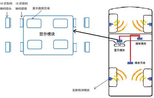
Figure 1 Schematic diagram of peripheral coding memory positioning technology
4 Antenna receiving near-transmitting field type The positioning technology receives four receiving antennas of the display module, which extend into the near field of 20-30cm of each tire respectively, and the receiving antenna is controlled by the numerical control microwave switch. When the information of a certain tire emission detection module needs to be received, only the microwave switch of the tire receiving antenna is turned on, and the others are turned off, and the tire pressure and temperature are displayed on the receiving display. The shortcomings of this positioning technology are: complex antenna wiring, high cost of microwave switches, RF switch isolation is not enough at the current technical level, there is a possibility of serial code (that is, information received from other tires); electromagnetic interference on the car may be It leads to positioning failure; the turn-on timing of the RF switch is according to a certain rule, and the transmission of the four tire emission detection modules is random, so when there is a RF switch near a tire, the emission detection module of the tire is just right No signal is transmitted, resulting in missing frames.
External code memory tire positioning technology External code memory tire positioning technology is a new type of TPMS tire positioning technology. As shown in Figure 1, the TPMS with external code memory is also composed of a transmission detection module and a reception display module, which is characterized in that a plug-in code memory is inserted in the reception display module, and each transmission detection module has a fixed The ID code is the same as the ID code of the corresponding code memory. When the tires are replaced or replaced, only the plug-in code memory needs to be replaced or replaced. The external code memory type tire positioning technology is simple by adjusting the correspondence between the ID code in the display module's code memory and the ID code in each emission detection module to convert the problem of re-identification into the problem of transposition setting of the ID code. , Effective solutions. Its plug-in operation is simple and reliable. Reading the code in the plug-in code memory circuit through I / O avoids reading the ID code wirelessly, which fundamentally solves the problem of interference.
Circuit design of external coded memory Figure 2 is a block diagram of the circuit implementation of the TPMS system. This article mainly describes the external plug-in coded memory circuit, and does not involve the circuit of the transmitter and the display itself. The design of the external coded memory circuit includes two parts, one is the connection part with the host, that is, the design of the connection circuit, and the second is the design of the memory.
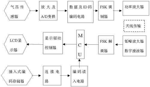
Figure 2 TPMS system circuit block diagram
1 Design of the connecting circuit The connecting circuit is the interface that connects the code memory circuit and the main controller circuit together. Since it is used in automobiles, the reliability of the interface should be considered. There are several designs as follows.
(1) Plug and socket 
Figure 3 shift memory circuit
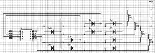
Figure 4 Diode memory matrix
Through the connection interface circuit of the plug and the socket, the advantage of this design is that it can use a universal socket on the market; the disadvantage is that the size is relatively large.
(2) The card holder makes gold-plated connectors on the PCB, that is, gold fingers. Plug the PCB directly into the socket through the golden finger, and connect it to the socket through the golden finger. This design is simple and low in cost, but it has poor resistance to vibration and low reliability.
(3) In the form of SIM card or IC, the storage circuit is made in the SIM card, and the code in the memory is read out through the SIM card or IC card interface; the interface is also made in the SIM card, and the interface design for SIM cartoon is adopted. The advantage is high reliability and small size, and the disadvantage is high cost. In the process of implementing the scheme, a plug with snap lock was selected on the connector circuit to ensure reliability.
2 The design memory of the code memory has many forms, which can be divided into two kinds of shift memory and matrix memory. At present, separate components can be used, or mature circuits on the market can be used. Circuits for automotive electronics applications have high requirements for electromagnetic compatibility. Here are a few specific circuits.
(1) The shift memory is shown in Figure 3. When writing data, every time the clock signal arrives, the D1 data is moved into the register, and all data is shifted to the right by one bit. When reading data, every time the clock signal arrives, all data is shifted to the left by one bit to read the value on the D1 port. The advantage is that it takes up less I / O ports. The disadvantage is that the reading speed is slower, and synchronization of the clock is required. Actual Above is the serial port.
(2) The matrix memory can be realized with switches, diodes, mos tubes, transistors or PLA. The advantage is that the reading speed is fast, and the disadvantage is that it takes up many I / O ports, which is actually a parallel port.
◠The diode storage matrix is ​​shown in Figure 4. The diode storage matrix is ​​actually a diode encoder. When one of the lines on PTB0 ~ PTB3 is low level and the remaining lines are high level; PTB0 ~ can be read out The value on PTB3; PTB0 ~ PTB3 have pull-up resistors, the ones connected with diodes are logic "0"; those not connected are logic "1". When the four lines on PTB0 ~ PTB3 are low level in sequence, PTB0 ~ PTB3 can read out four 4-bit codes, which together form a 16-bit code.
â— MOS tube and transistor storage matrix
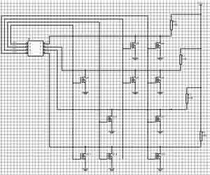
Figure 5 Tube storage matrix
As shown in Figure 5, the MOS tube and transistor memory matrix are in principle the same as the diode memory matrix, except that the diode is replaced with a MOS tube and transistor. In the choice of memory circuit, in order to avoid the influence of the clock on the electromagnetic environment of the car, the shift memory was abandoned, and the matrix memory was selected. Although the number of I / O ports occupied is large, the reliability is high and the read The retrieval speed is fast. There are two schemes selected, one is a high- and low-temperature-resistant parallel port data storage chip, and the other is a matrix memory circuit using diodes. The advantage is that the circuit is simple and reliable and the cost is low.
Implementation of external code memory tire positioning technology Each emission detection module corresponds to a plug-in external code memory (ID code plug). The ID code stored in the coding circuit in the code plug and the corresponding emission detection module are solidified in the memory. The ID code is the same. There is an ID identification code encoding socket next to each tire data display area on the display module. When a plug-in encoding memory is inserted into the ID identification code encoding socket, the receiver reads the ID code in the plug-in encoding memory by locating the ID code socket, and Establish a corresponding positioning relationship between the ID code and the corresponding tire data display area. At each start-up, the receiving display module reads the ID code inserted in the plug-in external coding memory (ID code plug) on ​​each socket, and then resets the ID code stored in the receiving display module MCU to correspond with the tire. Relationship information, and save it. After the corresponding information transmitted by the transmitting module, the receiving module reads the ID code therein, and then determines which signal is sent by the tire according to the corresponding relationship between the ID code in the receiving display module MCU and the tire, and the pressure and temperature The information is displayed in the corresponding area. When the user needs to transpose the tire, the corresponding plug-in code memory can be transposed. When the device is turned on next time, the receiving display module resets the ID code stored in its MCU and the corresponding positioning information of the tire to ensure that the information is displayed in the correct position. If the user finds that a certain transmitter is damaged, it is only necessary to purchase a launch detection module kit (plug-in external code memory as an accessory) on the market. Because a plug-in external code memory is attached to the transmitter, you only need to unplug the damaged external code memory of the transmitting module and re-insert the random new plug-in code memory. When the device is turned on next time, the receiving display module resets the ID code stored in its MCU and the corresponding positioning information of the tire to ensure that the signal emitted by the new transmission detection module is displayed in the correct position.
Lithium Battery Pack For Hybrid Electric Locomotive
Lithium Battery For Electric Car,Cylindrical Battery,2000-2500Kw Lifepo4 Battery System,Ce Certificated Lithium Battery
Henan Xintaihang Power Source Co.,Ltd , https://www.taihangbattery.com