A New OFDM Joint Synchronization Algorithm Based on Single Training Symbol
0 Preface
Orthogonal Frequency Division Multiplexing (OFDM) is a multi-carrier modulation method. The basic idea is to convert high-rate source information streams through serial-parallel conversion into N low-rate parallel data streams. Channel data streams are modulated onto N mutually orthogonal sub-carriers and transmitted in parallel. Because OFDM has the ability to resist multipath fading and frequency selective fading, and at the same time can improve the spectrum utilization rate of the system, the OFDM system is particularly suitable for high-speed data transmission in a multipath wireless channel environment. However, compared with the single carrier system, the OFDM system has stricter requirements on synchronization and is more sensitive to synchronization errors. If the synchronization is not accurate, it will directly affect the orthogonality between subcarriers, causing intersubcarrier interference (ICI) and Inter-symbol interference (ISI) seriously affects the performance of OFDM systems. The OFDM synchronization algorithm has always been a research hotspot of scholars. In this paper, through the study of the classic Schmidl & Cox time-frequency joint synchronization algorithm, an improved algorithm is proposed, that is, an OFDM joint synchronization algorithm based on a single training symbol. Through software simulation, it is concluded that the new joint synchronization algorithm has better synchronization accuracy.
1 Schmidl & Cox time-frequency joint synchronization algorithm
Schmidl and Cox proposed a time-frequency joint synchronization algorithm based on training symbols. In this synchronization algorithm, the training sequence selects two OFDM symbols, the first symbol is used for symbol timing synchronization and fractional frequency offset estimation; The second symbol is used for integer frequency offset estimation. Figure 1 shows a schematic diagram of the training sequence structure of Schmidl & Cox algorithm. 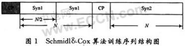
In Figure 1, the first symbol of the training sequence is composed of the same two parts before and after in the time domain, and the data modulated on the even multiple subcarriers of the second training symbol has a differential relationship with the data of the corresponding position of the first symbol The estimation of integer frequency offset is completed by using this relationship.
Since the first half and the second half of the first symbol in the training sequence are exactly the same, the effect of carrier frequency deviation on the signal is only phase deflection. If the data in the first half is conjugated and multiplied with the data in the second half (interval T / 2), the influence of the channel can be eliminated, and there will only be a phase difference of φ = πT △ f. At the beginning of the training symbol, each pair of corresponding data is multiplied to have this phase approximately, so this phase difference will accumulate after the summation and reach a larger amplitude.
The timing function used by Schmidl & Cox algorithm can be expressed as: ![]()
Since there is a "platform" area in the output of M (d), and this area is not precise, the correlation peaks of the timing function are distributed within a certain area. Figure 2 shows the output waveform of M (d) under the Gaussian channel. Among them, SNR = 15 dB, information data is 4 OFDM symbols, each OFDM symbol length is 1 024, cyclic prefix length is 128, the insertion position of the training sequence is located in the middle of the information sequence. It can be seen that the output amplitude of the training sequence region M (d) is significantly higher than that of other information data regions, and the completion of symbol timing takes advantage of this feature.
2 New time-frequency joint algorithm
The structure of the training symbol is directly related to the performance of the algorithm. Schmidl & Cox algorithm training sequence structure is modified to a certain extent. The new training symbol structure is shown in Figure 3. Figure 4 shows the specific process of this transformation. 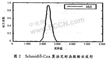
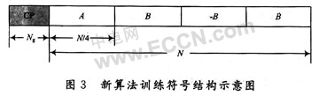
In the time domain, the training symbol is composed of four parts of equal length, where A itself has a repeating structure, A and B have a symmetric conjugate relationship, and the data A is obtained by performing IFFT on the modulated N / 4 length sequence The method realizes that this N / 4 length sequence sends a PN sequence at an even subcarrier position and sends a zero at an odd subcarrier position. After IFFT, the repeating structure of data A itself can be realized. After A is taken symmetrically and conjugated , Get B, and then take the opposite of B to get -B.
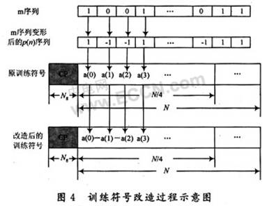
In order to obtain better symbol timing performance, the proposed algorithm is to avoid the use of timing functions that exhibit a "platform" phenomenon, and hope that the constructed timing function can form a single, sharp correlation peak at the correct synchronization position, which is more suitable for use. Peak detection method to achieve symbol timing synchronization. The new algorithm transforms the training symbol, the specific operation is as follows: multiply an equal length m sequence p (n) in front of the data A of the first part of the training symbol, so the data of the first part becomes p (n) A, training The remaining three parts of the symbol are obtained in the same way as above.
Because m-sequence has good autocorrelation characteristics, p (n) is obtained by mapping m-sequence. Take the m sequence of length N / 4, the form is "0", "1" sequence, the mapping method is to replace "0" in the sequence with "-1", and the new sequence after transformation is p (n). It needs to be explained that when introducing p (n) and constructing p (n), the significance of deforming the m sequence lies in the random introduction of "-1" and "1" in the training symbols, which is not caused by the estimation of decimal frequency deviation. Based on the influence, the use of its good autocorrelation characteristics can further optimize the symbol timing synchronization performance.
According to the characteristics of the training symbol after transformation, the timing function proposed by the new algorithm is: 
In the formula: d represents the time serial number, moves one sample value along the time axis each time, searches for the time serial number that makes M (d) reach the maximum value, which is the starting moment of the training symbol. The completion of symbol timing is determined by checking the maximum value of M (d). It can be seen that the expression of the timing function in the new algorithm is the same as the Schmidl & Cox algorithm. What changes is the form of the correlation function expression P (d). According to the special structure of the training sequence, the correlation function is defined as the sum of three pairs of data segment operations Since the third part of the data in the training sequence is the opposite number after the first part of the data is symmetrically conjugated, a factor (-1) k is introduced into the P (d) expression.
Compared with Fig. 2, the output waveform of the symbol timing function of the new algorithm shown in Fig. 5 shows impulse-like peaks, effectively overcoming the top platform and both sides of the peak of the symbol timing function output waveform in the Schmidl & Cox time-frequency joint synchronization algorithm The error caused by the slow decline of the value is conducive to the accurate completion of symbol timing synchronization. Fig. 6 is a signal-to-noise ratio-mean-square error graph obtained when the above two synchronization algorithms are used to simulate an OFDM system. 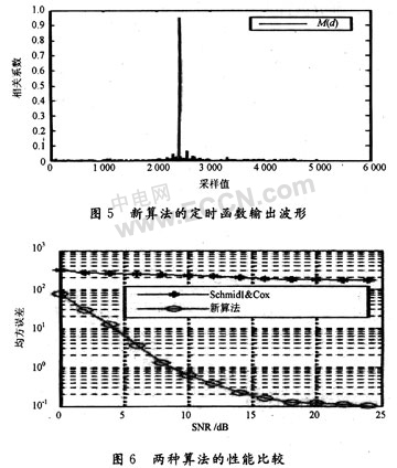
3 Conclusion
As can be seen from the results in Figure 6, the symbol timing synchronization performance of the new algorithm is greatly improved compared to the performance of the Schmidl & Cox time-frequency joint synchronization algorithm, and the new algorithm achieves the Schmidl & Cox time-frequency joint on the basis of a training symbol. The synchronization algorithm has considerable frequency offset estimation performance, and the synchronization overhead used is small, which is beneficial to further improve the frequency band utilization of the OFDM system.

Led Modules,5W Led Module,Ceiling Module,Led White Light
Shenzhen Dianjiang Engineering Co. LTD , https://www.isourceled.com