Four-wheel independent drive electric vehicle high-speed CAN network data analysis technology
With the development of electric vehicles, CAN bus communication technology is more and more widely used. It can be used for four-wheel independent drive control on pure electric vehicles, as well as active safety systems such as brake anti-lock brake system (ABS) and electronic stability device (ESP) To facilitate the implementation.
When designing a CAN bus communication system, there is always the problem of diagnosis and analysis of CAN data. If the problem cannot be solved, the design cannot be completed. This article is based on the USB_CAN tool Kvaser Leaf Professional HS, with the help of the Visual Basic environment, a data analysis system is developed on the PC, and CAN communication is implemented between the analysis system and the motor control board of the four-wheel independent drive electric vehicle. Through the diagnosis and analysis of the CAN bus data, the design of the CAN bus system can be better completed.
Four-wheel independent drive electric vehicle control strategy
The distributed four-wheel electronic differential system used in the electric vehicle physical model is composed of a central controller, four electric wheel controllers and a CAN bus network. Its layout on the electric vehicle physical model is shown in Figure 1. . 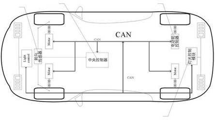
Figure 1 The layout of the distributed four-wheel electronic differential system on the body
In this distributed system, the electronic differential algorithm based on four-wheel independent control is divided into two parts: vehicle differential algorithm and speed control algorithm. The speed control algorithm is for each electric wheel speed. The central controller and the four electric wheel controllers are connected into a real-time control network via CAN bus.
In the system control process, the central controller obtains the vehicle steering angle signal from the steering sensor and the vehicle speed setting signal from the handlebar through A / D sampling. After the vehicle differential algorithm, the current four wheels are respectively obtained The proper speed, and use this result as the speed control setting value of the corresponding wheel at the current time, and send it to the corresponding electric wheel controller through the CAN bus. The four wheel controllers use the speed setting value received from the CAN bus as the control target, and use the electric speed control algorithm to control the respective electric wheels, so that the actual speed of each electric wheel can meet the requirements of the vehicle differential algorithm in real time. In order to achieve smooth steering of electric vehicles.
Four-wheel independent drive electric vehicle CAN control network
Through the CAN bus, the central controller of the four-wheel drive electric vehicle transmits the set values ​​such as the speed of the wheels to the controller of each wheel, and at the same time, the motor controllers feed back the actual speed and other information to the central controller through the CAN bus. The topology of the CAN network is shown in Figure 2. 
Figure 2 CAN control network topology
The entire network contains five CAN nodes: four electric wheel motor controllers a, b, c, d, and an electric vehicle central controller e.
When designing the application layer protocol, a reasonable bus arbitration priority must be arranged for the bus messages according to the actual application to improve the real-time nature of CAN communication. In this application, the downstream data, that is, the control commands sent by the central controller to each electric wheel motor controller, have higher priority than the upstream data, that is, the feedback information of each electric wheel motor controller. In addition, the commands sent from the central controller to the four wheel controllers must be synchronized to provide a reliable premise for subsequent control.
Comprehensively considering the above factors, this paper designs the CAN data message ID system shown in Table 1.
The motor controllers a, b, c, and d respectively control the left front wheel, the right front wheel, the left rear wheel, and the right rear wheel of the electric vehicle. The CAN message data field structure issued by the central controller is shown in Figure 3. 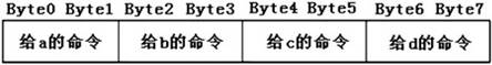
Figure 3 Central controller CAN message data domain structure
The CAN data with IDs 0x010 and 0x020 issued by the central controller represent the set values ​​of speed and torque, and the corresponding actual values ​​are analog. Here, a 16-bit fixed-precision fixed-point number is used. In the 16-bit data, the upper 9 bits represent integers, and the lower 7 bits represent decimals, that is, fixed-point numbers in 9Q7 format. For the CAN data with ID 0x00F issued by the central controller, the command sent to each motor controller is also 16-bit data, the lower 8 bits indicate the brake command, and the higher 8 bits indicate the control mode selection command.
The structure of the CAN message data field where the four motor controllers feed back the current state information to the central controller is shown in Figure 4. 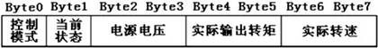
Figure 4 Motor control feedback status information structure
There are two ways to trigger CAN bus messages: event trigger and time trigger. The former is suitable for sending discrete switching state quantities in time, such as brake commands and control mode selection commands; the latter is suitable for sending continuously changing analog quantities, such as speed setting values ​​and torque setting values. Because the above two types of bus information are combined in this control system, the event trigger and time trigger are combined to send.
About Kvaser Leaf Professional HS
Kvaser Leaf Professional is a single-channel USB interface for CAN and LIN. The device provides the possibility of simply connecting several interfaces to a PC. It is convenient to connect multiple Kvaser Leaf devices to the same USB Hub without additional Connection. In addition, it also has very good EMC (Electro MagneTIc CompaTIbility) performance and plug-and-play features. At the same time, since multiple devices can be connected to one USB Hub, each device can be powered by the Hub, which has very low power consumption.
The library functions provided by Kvaser are very rich, and users can call the corresponding library functions according to their needs to flexibly process CAN bus data.
Ceramic Capacitor (ceramic capacitor);Ceramic condenser) is also known as porcelain capacitor or monolithic capacitors.As the name implies, ceramic dielectric vessel is a ceramic capacitor with dielectric material.According to different ceramic materials, this kind of capacitor can be divided into low-frequency porcelain dielectric vessel with capacity of 1-300 pF and high-frequency porcelain dielectric vessel with capacity of 300-22 000 pF.According to the structure type classification, can be divided into picture capacitor, tubular capacitor, rectangular capacitor, chip capacitor, piercing capacitor and so on.
Ceramic Capacitor
Ceramic Capacitor,White Ceramic Capacitor,Smd Ceramic Capacitor,Multilayer Chip Ceramic Capacitor
YANGZHOU POSITIONING TECH CO., LTD , https://www.yzpstcc.com