Abstract: In order to avoid the phenomenon of hot shaft cutting during the operation of high-speed trains, a shaft temperature centralized monitoring system was designed using 2.4GHz wireless communication technology. The system consists of a monitoring node and a monitoring platform installed on the axle; the monitoring node uses ATmega128L as a microcontroller The temperature sensor PT100 is used to collect the shaft temperature, and the wireless module nRF24L01 is used to transmit the data. The monitoring station is mainly responsible for the centralized reception, processing, display and storage of the data sent by each monitoring node; when the shaft temperature is too high, the alarm reminds Drivers take emergency measures to avoid accidents; experiments have shown that the system can accurately measure the shaft temperature status of running trains, and give the experimental results and analysis.
Keywords: centralized axle temperature monitoring; train safety; wireless transmission.
0 Preface
During the high-speed operation of the train, the frequent impact of the locomotive and the rail will cause the heating of the vehicle bearing. When the bearing wears and generates defects, it will cause machine damage and affect the normal operation of the vehicle. Even the hot-cut shaft will directly cause the train to malfunction. The overturning caused huge economic losses to the country and society in railway transportation. At present, most of China's infrared shaft temperature monitoring systems are used, but this equipment is susceptible to external environment and the detection point is affected by the body swing. It is difficult to locate and so on, which makes the high shaft temperature low alarm redemption rate, high false alarm rate, and the outside world. Factors can easily cause great interference to its working state, and the distortion is serious. It is very likely to give the wrong temperature prompt and affect the normal operation of railway transportation [1-2]. In view of this situation, a high-speed train axle temperature centralized monitoring system with a simple system, small layout, high sensitivity, and fast ability to send and receive information has been designed to detect whether the temperature of the running train bearings is too high, such as the axle temperature exceeding The alarm signal is issued when the value is set, and the locomotive driver can stop the inspection in time, effectively reduce the accident rate, avoid the huge economic loss caused by the accident, and maintain the normal operation of the railway transportation.
1 Overall system design
High-speed trains are composed of multiple cars, each train car has two axle frames, each axle frame has two axles, and each axle has two axle boxes at both ends. In the design, an axle temperature sensor is installed on each axle box, and a monitoring node is provided on each axle frame. The vast majority of train axle temperature alarm devices still follow the traditional single-vehicle decentralized alarm mode. In consideration of the problem that trains often change the locomotive head and carriage, 2.4G wireless communication transmission system is selected as the transmission method.
In order to prevent data congestion, round-robin-answer mode is used for communication, which greatly improves the communication quality and reliability. The system is mainly composed of multiple monitoring nodes and a monitoring station deployed in the cockpit. The system structure is shown in Figure 1.
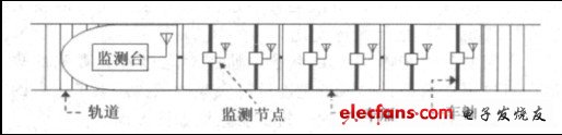
Figure 1 Schematic diagram of the system structure
The monitoring node converts the analog signal into a digital signal through a temperature sensor, and transmits the axle temperature of each axle of the train to the monitoring console installed on the locomotive in real time for analysis and display for the locomotive driver or ground vehicle maintenance department to monitor at any time The change of axle temperature when the vehicle is running. In the course of train transportation, when the shaft temperature is abnormal, the monitoring station can send an alarm signal to the driver, reminding to stop in time to take certain measures to eliminate the fault, reducing the probability of accidents caused by high shaft temperature during the operation of the locomotive, thus Ensure the safety of train operation.
2 Hardware structure
The wireless node hardware of the system is mainly composed of microcontroller ATmega128L, temperature sensor PT100, wireless communication module nRF24L01, memory K9F5608 and power management module. The monitoring station also includes an alarm and display unit.
The main function of the controller unit of the hardware component is to control the temperature sensor to collect the axle temperature information of the train, process and forward the information, and analyze and display the received data. The data collection unit mainly collects shaft temperature information through a temperature sensor. The wireless communication unit is used to send the collected shaft temperature data and communicate with the train monitoring station in real time. The hardware configuration of the node is shown in Figure 2.
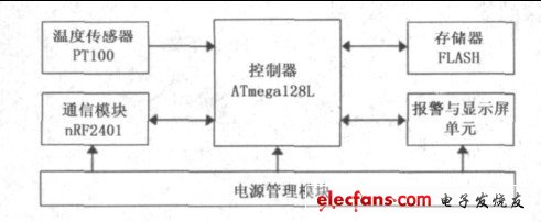
Figure 2 Node hardware composition
2.1 Microcontroller ATmega128L
Considering that the controller must not only meet the requirements of the system, but also maintain the characteristics of low power consumption and small size, the 8-bit microcontroller ATmega128L is selected. Compared with other general-purpose 8-bit microcontrollers, it has a very rich Resources, the performance is up to 16MIPS when working at 16MHz, with on-chip 128k bytes of program memory, 4k bytes of data memory and 4k bytes of E2PROM; with two 16-bit timers / counters; with 53 general purpose O port line, real-time clock RTC, two USARTs, SPI serial interface that can work in master / slave mode, 8 10-bit ADC, two 8-bit PWM, JTAG test interface compatible with IEEE1149.1 specification for On-chip debugging, and 6 power saving modes that can be selected by software. The ADC port of the controller is connected to the output of the PT100, the SPI interface is connected to the wireless communication module nRF24L01 to realize data transmission and reception, the PWM port is used to drive the alarm unit of the monitoring station, and the data bus and address bus are used in conjunction with the memory.
2.2 Wireless communication module nRF24L01
nRF24L01 is a monolithic RF transceiver working in the 2.4GHz ~ 2.5GHz ISM band. It has built-in frequency synthesizer, power amplifier, crystal oscillator, modulator and other functional modules. It supports two data transmissions: Shock-Burst and Enhanced Shock-Burst. Way, in which the output power and communication channel can be configured through the program. nRF24L01 has low power consumption. When transmitting at -6dBm, the working current is only 9mA. When receiving, the working current is only 12.3mA. A variety of low-power working modes (power-down mode and idle mode) make energy-saving design more convenient. Interface The highest rate can reach 8Mbps, the working voltage is 1.9 ~ 3.6V, the SPI interface is used to send and receive data, the wireless data transmission rate is up to 2Mbps, and it has automatic answer and automatic retransmission functions. The selection of output power, channel allocation and protocol can be set through the SPI interface [3].
2.3 Temperature sensor PT100
Commonly used contact temperature sensors include thermocouples, thermal resistors, semiconductor quartz crystals, etc. The resistance value of platinum thermal resistance at 0 ° C is called R (0 ° C) and the resistance value at 100 ° C is called R (100 ° C) and R (100 ℃) / R (0 ℃) is called the ratio W100. The temperature sensor of the monitoring node adopts platinum electric PT100, the meaning of PT100 is (0 ℃), the nominal resistance value is 100Ω, under the action of temperature, the platinum thermal resistance wire The resistance value changes with the change, and the relationship between resistance and temperature, that is, the indexing characteristic is completely equivalent to the IEC standard, so PT100 is mainly used to measure the temperature of -200 ~ +600 ℃. The resistance value of platinum resistance has a non-linear relationship with temperature, so nonlinear correction is required [4]. The correction is divided into analog circuit correction and microprocessor digital correction. Analog correction has many ready-made circuits. Its accuracy is not high and it is easily affected by interference factors such as temperature drift. Digital correction needs to be used in a micro-processing system. Correspond to the temperature and store it in EEPROM, according to the actual measured value in the circuit to calculate the corresponding temperature value by looking up the table. There are two commonly used Pt resistance sampling circuits: one is a bridge temperature measurement circuit; the other is a constant current source temperature measurement circuit.
The monitoring node used in the system is the first bridge current temperature measurement circuit, which has the advantages of high measurement accuracy, large measurement range, good repeatability and stability.
2.4 Memory K9F5608
The memory K9F5608 is a 32MBytes capacity NAND Flash chip produced by Samsung. It is used to store temporary shaft temperature data. When the communication is interrupted, the data can be stored in K9F5608. After the communication returns to normal, the data will be sent to the monitoring station. It has an 8-bit data / address multiplexing interface and control signals such as CLE, ALE, WP, R / B, and CE. The hardware interface is relatively simple, but the read and write timing is relatively complicated, and commands, addresses, and data must be sent in sequence. Actually need to input 24-bit address for addressing. Because the interface between the chip and the controller ATmega128L is an 8-bit address data multiplexing line, it takes 3 cycles to complete the input of 24-bit address [5]. The peripheral circuit of memory K9F5608 is shown in Figure 3.
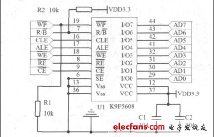
Figure 3 K9F5608 peripheral circuit
The PA port of the controller ATmega128L completes the transmission of Flash data, address and commands; the PG port of the controller is used to complete the selection of Flash transmission status, such as CLE, ALE, R / B, CE, etc .; RD signal to select whether FLASH is read or written, the general sequence of transmission on the bus is:
Command-> Address-> Command / Data.
Kitchen Appliance,Double/Single Burners Stove,Smart Kitchen Appliance,Save Energy Induction Cooker
JOYOUNG COMPANY LIMITED , https://www.globaljoyoung.com