1 Introduction
According to the 3GPP specifications, currently LTE to LTE-A are mainly divided into three versions, namely Release 8, Release 9, and Release 10. That is to say, 3GPP introduced the LTE standard from Release 8; Compared with Release 8, Release 9 adds "positioning reference signal", "broadcast multicast single frequency network", and "dual stream beamforming" to the definition of the physical layer. "In Release 10, the physical layer has added" carrier aggregation "," shared channel clustering "and other characteristics, LTE Release 10 is also called LTE-Advanced or LTE-A.
For network equipment manufacturers, whether in the research and development stage or production stage, the radio frequency test of equipment such as base stations and repeaters uses the method of vector signal source and signal analyzer. Taking the LTE base station radio frequency test as an example, a manufacturer uses a vector signal source to generate an LTE uplink signal, a simulated terminal transmits an uplink signal to perform reception characteristic test and performance test on the base station, and uses a signal analyzer to test the radio frequency index of the downlink signal transmitted by the LTE base station.
For chip and terminal manufacturers, vector signal sources and signal analyzers are also used in the early stages of R & D. Similar to base station testing, chip and terminal manufacturers use vector signal sources to generate LTE downlink signals and simulate base station transmit signals to test the terminal's receive sensitivity, throughput rate, and other characteristics. The signal analyzer is used to test the radio frequency index of the uplink signal transmitted by the terminal.
It can be seen that vector signal sources and signal analyzers, as general RF test instruments, are widely used in RF testing of LTE and LTE-A equipment.
2 LTE and LTE-A signal generation solutions
As mentioned above, the vector signal source needs to be used to generate LTE / LTE-A uplink or downlink signals for testing the reception performance of LTE equipment. The following is based on 3GPP's LTE / LTE-A specification document, briefly introduces how to use R & S signal source SMU200A to generate LTE / LTE-A test signals.
First, taking the radio frequency test of network equipment in LTE Release 8 as an example, the test is mainly conducted according to Chapters 7 and 8 of the 3GPP 36.141 specification. Among them, the seventh chapter is the base station reception test. The signal source needs to be able to generate useful LTE signals, white noise signals, and interference signals. The signal source SMU200A can realize all three signals simultaneously within one source. Chapter 8 belongs to the base station performance test part, which mainly examines the base station's performance and hybrid automatic retransmission in typical fading scenarios. Take the 3GPP 36.141 8.2.2 "Uplink Delay Adjustment" test case as an example. The background of this test case is to input two analog terminal signals to the base station. One of these two terminals is a fixed terminal and the other is a mobile terminal. The delay between the base stations is constantly changing. In order to correctly receive the data packets transmitted by the mobile terminal, the base station needs to send the "Hybrid Automatic Retransmission (HARQ)" information to the mobile terminal. The mobile terminal does this based on the feedback signal of the base station. The transmission time is automatically adjusted, and the signals of both terminals are loaded with additive white Gaussian noise signals. At this time, observe whether the change of the base station's throughput rate meets the specifications. The test block diagram given by 3GPP is shown in Figure 1.
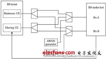
Figure 1 Connection diagram of upstream delay adjustment test case
According to Figure 1, to complete this test, you need: two signal sources, one simulated fixed terminal, and one simulated mobile terminal, and the signal source of the simulated mobile terminal needs to be able to receive HARQ information sent by the base station and respond correctly; The noise signal generator is used to generate a noise signal; the fading simulator is used to simulate the time-varying characteristics between the mobile terminal and the base station. The R & S signal source SMU200A has a high degree of integration. It can realize two independent signal transmissions within a signal source, and simulate the fading characteristics and additive white Gaussian noise signals within the signal source, that is, within a signal source. All the above features. A single signal source SMU200A test uplink delay adjustment configuration interface shown in Figure 2.
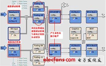
Figure 2 SMU200A test uplink delay adjustment configuration interface
Electronic motors specilized for honeycomb blinds.
Roller Blind Drive,Skylight Shade Motor,Honeycomb Blinds Motors,Roller Blind Motor
GUANGDONG A-OK TECHNOLOGY GRAND DEVELOPMENT CO.,LTD. , https://www.a-okmotor.com