I have been busy for a while, so I didn't have time to write a blog post. After finishing all sorts of things, I continued the research of FPGA. Methods for completing FPGA designs using Verilog HDL language and schematic input have been tested, and more advanced are based on System Generator and EDK/Microblaze-based methods. In order to quickly convert the motor control algorithm that has been developed by Matlab simulation into an algorithm for FPGA, firstly, the FPGA development based on System Generator is studied, and several algorithms are selectively implemented to prove its effectiveness. Here, I will write some of the experiences in the development process, and welcome everyone to share and communicate.
Introduce the hardware and software environment in advance:
The ISE version is Xilinx ISE Design Suite 12.1 (including System Generator 12.1, but the famous AccelDSP component can not be found); Matlab version is MATLAB R2010a Win32 version (Simulink is 7.5 version), hardware development board has DigilenTInc Spartan3E XC3S500E development board And the Spartan3 XC3S400 experiment board made by myself.
The first is to install Matlab. It should be noted that the installation path of Matlab must start with English, and the number can contain numbers in the middle; secondly, there can be no spaces in the path, otherwise System Generator will not recognize the path of Matlab. Then install ISE 12.1, and then click “System Generator MATLAB Configurator†in “C:\Documents and SetTIngs\All Users\Start Menu\Program\Xilinx ISE Design Suite 12.1â€. If Matlab is installed correctly, System Generator will recognize it. Maltab, otherwise you need to manually select the path of Maltab; there is a version limit, that is, ISE/System Generator12.1 can only fully support Maltab2009a/b, and only support for Maltab2010a (the middle problem is that Resource EsTImator is used once) After that, it will not work properly anymore, I don't know if it is the reason for beta).
Then you can start Matlab, create a new mdl simulation file, and open Simulink Library Browser to switch to Xilinx Blocket. If you open Xilinx Blocket for the first time, you need to have a process to create Xilinx cache. It takes a long time, don't use it as a computer. The suspended animation. There are also two Xilinx menus that are Xilinx Reference Blockset v12.1 and Xilinx Blockset v12.1, which will be discussed in more detail later.
Enter the development steps below. First of all, there must be a System Generator toolbox (in Xilinx Blocket-tools) in each project, which can be configured here.
[1]. The type of project generated by System Generator, such as ISE project, EDK project, etc., can even directly produce .bit configuration files;
[2]. The model number of the device, including package, speed, etc.
[3]. System Generator output path (folder);
[4]. Comprehensive tools (such as XST, Synplify, etc., often can not find Synplify, simply XST is good);
[5]. Programming language selection: only VHDL and Verilog HDL;
[6]. You can choose whether to produce test files;
[7]. Configure the clock of the FPGA and select the clock management mode. Here is the configuration of the clock pin, but you should not fill it first, otherwise there will be many warnings in the following synthesis; secondly, if DCM mode is selected, It can only support Virtex4\5 devices (prompted when compiling with Spartan3, 3E; strange why it is not said to support the latest Spartan6, Virtex6 devices);
[8]. Finally, select the simulation cycle of Simulink and the display mode of each module (such as selecting default to display the default value of each module, and selecting Sampling Frequency to display its clock frequency on the input and output pins of each module, such as 50MHz, 10MHz, etc.).
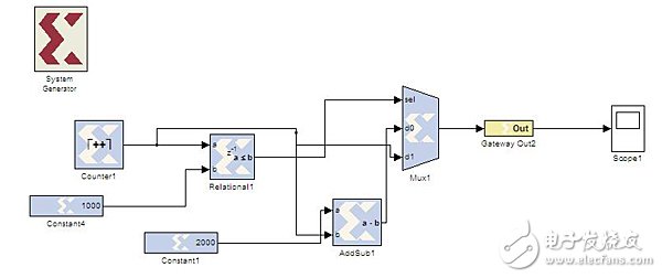
After the system generator configuration is completed, the rest of the simulation environment is built and run in the same way as the Simulink common application, except that the module that is dragged from the Xilinx menu can be physically implemented (ie, integrated); The connection between other modules in the Simulink library and the Xilinx module uses Gateway In and Gateway Out as interfaces.
After building a complete system, connect the variables you need to observe to the oscilloscope via Gateway Out. Click on the Simulink Run button to observe the results. System Generator's error mechanism is very strict, even if the number of data bits is wrong, it will stop emulation and report an error.
After the simulation is correct, the operations that can be run are more abundant, such as calling Modelsim for simulation (the .do file is automatically produced in the output folder of System Generator), and the Resource EsTImator is called to estimate the resource (the process is quite long, because the process needs to be integrated) Wait. Once you're done, click Generate in the System Generator toolbox to produce the ISE project (.xise) in the output folder.
Open the production ISE project, the next operation is no different from usual, except that the code here is automatically generated :). Of course, there is one more point that needs to be specifically addressed. In the generated constraint files in the project, there are only timing constraints, and there is no pin constraint (although there is no pin constraint, it is also possible to integrate, map, and generate download files, which is a bit strange) . You can add inputs, outputs, and signals to your project, and then assign pins to the Floorplan. After synthesis, mapping, generating download files, burning into the PROM, you can run.
Finally, I have a little experience in the development and debugging of System Generator:
[1]. Some of the logical structures that Xilinx Blocket does not have, such as the case---switch statement, are more troublesome to use with modules. You can write them in Matlab's m file and save them as Matlab functions, then use Xilinx Blocket's Mcode. The module is called, which is much simpler than the module;
[2]. The processing of floating point numbers is a big trouble. Fortunately, Xilinx Blocket provides Xfix statements, which can convert floating point to the required width and number of fixed points, such as a = xfix({xlUnsigned, 8, 3}, 1.53), the floating point number 1.53 is converted to an unsigned number, the first 8 bits represent integers, and the last 3 bits represent decimals;
[3]. Xilinx Blocket some modules do not consume hardware resources, such as the scale module; others are consumed, such as the shift module; these detailed instructions are in the help of each module;
[4]. Some modules in Xilinx Blocket are not necessarily applicable to selected devices, such as DSP48, DSP48E, etc. In this case, it is necessary to combine the characteristics of specific devices.
In the rectifier circuit; the use of diodes in series can increase the back pressure withstand value (usually the sum of the back pressure of all diodes, but it is best to use diodes of the same specification).
In the voltage stabilization circuit; the series connection of the diode is equal to the sum of the voltage stabilization value of the diode. The use of diodes in parallel is theoretically the sum of rated currents, but considering that it is impossible to be absolutely symmetrical, they can only be used below 80% of the total.
TVS transient suppressor diodes work in the same way as regulator diodes, but there are structural differences.The biggest difference is that the PN junction area composed of the general regulator diode is very small, it can withstand the reverse current is small.
Transient Voltage Suppressor,Transient Voltage Suppressor Diode,Series diode
Changzhou Changyuan Electronic Co., Ltd. , https://www.cydiode.com