When you can modify the LED led_test.sh, change the speed of the LED lighting, and the order, you must know what happened, based on a simple script, on the Linux user layer control board A piece of hardware, say, a light.
For the brothers who are accustomed to no operating system streaking C/assembly in the MCU environment, the above problem seems to be somewhat redundant. Directly read and write operations on an address, this address is decoded, the corresponding pin, connected to the board On the LED, can you control the LED?
This is a long story. In short, Linux deliberately divides user space and kernel space in order to give each process a separate address space. Kernel space can operate on physical addresses, and user space is just virtual addresses. The kernel interfaces with the user space program and uses a special file system. That is, it looks like a file, actually connected to the system of systems and devices. Older devfs file systems are located in the device driver /dev, or procfs are located in /proc. Of course, there is a relatively new sysfs file system.
Led_test.sh, which uses the sysfs file system. The characteristics of this file system, mainly driven by a layer of hardware, such as the first bus driver, then a USB driver, the driver of the device mounted on the USB. This is much clearer than a /dev device driver including all relevant device levels. Only after the Linux kernel 2.6.
First sensible understanding of sysfs, input in any terminal window of ZED
Sudo echo 61 > /sys/class/gpio/export
Sudo echo out > /sys/class/gpio/gpio61/direcTIon
Sudo echo 1 >/sys/class/gpio/gpio61/value
Sudo echo 0 >/sys/class/gpio/gpio61/value
You can light or turn off the LD0 lamp by hand.
When you enter the command, what happened, how is the signal passed? First, let's take a general look at the details. The details will be explained in detail in the subsequent chapters of the book.
In the first step, the device driver controls the registers of the GPIO. This needs to be done to the Linux device driver. For related introductions, please refer to the book found in section 13.2.
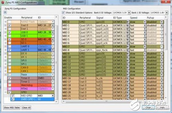
The second step, then what is the register address of GPIO, how to control it? We can find it in Xilinx ug585
The third step, how is GPIO on the PL side, that is, the FPGA is connected to the pin of the chip? Need to refer to the hardware part of this design
Hardware engineering used by the linaro-ubuntu demo on zedboard.
Among them, we can find the following constraints for system.ucf in zedboard. For example, the LD0 lamp is the processing_system7_0_GPIO<7> on the PS side. It is connected to pin T22 by PL measurement.
###########################################
# #
# On-board LED's #
# #
###########################################
Net processing_system7_0_GPIO<7> LOC = T22 | IOSTANDARD = LVCMOS33; # LD0
Net processing_system7_0_GPIO<8> LOC = T21 | IOSTANDARD = LVCMOS33; # LD1
Net processing_system7_0_GPIO<9> LOC = U22 | IOSTANDARD = LVCMOS33; # LD2
Net processing_system7_0_GPIO<10> LOC = U21 | IOSTANDARD = LVCMOS33; # LD3
Net processing_system7_0_GPIO<11> LOC = V22 | IOSTANDARD = LVCMOS33; # LD4
Net processing_system7_0_GPIO<12> LOC = W22 | IOSTANDARD = LVCMOS33; # LD5
Net processing_system7_0_GPIO<13> LOC = U19 | IOSTANDARD = LVCMOS33; # LD6
Net processing_system7_0_GPIO<14> LOC = U14 | IOSTANDARD = LVCMOS33; # LD
The fourth step, how to connect the T22 pin to the real lamp, you need to refer to the ZED board documentation:
2.7.3 User LEDs
The ZedBoard has eight user LEDs, LD0 – LD7. A logic high from the Zynq-7000 AP SoC I/O causes the LED to turn on. LED's are sourced from 3.3V banks through 390Ω resistors.
Signal Name SubsecTIon Zynq pin
LD0 PL T22
LD1 PL T21
LD2 PL U22
LD3 PL U21
LD4 PL V22
LD5 PL W22
LD6 PL U19
LD7 PL U14
LD9 PS D5 (MIO7)
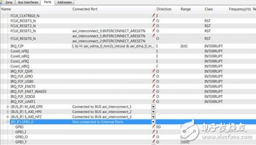
We can see that LD0-LD7 are all PL parts, which means that these are EMIOs, which are connected from the pins of the PL. So, how does EMIO define the processing_system7_0_GPIO port in the design? Need to see xps
2. We can find this tag in the ports tag.
3. At the same time, this definition will automatically appear in system.mhs
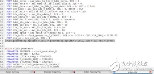
In this way, from the script of the operating system to the lighting of the LED, we found the software side, the PS side, the expandable IO side, the PL side all relevant documents and signals, and completed the simplest one through software, hardware, I/ O, the board's All Programmable tour.
LED Video Wall And LED Display Screens
We strive to create products which are environmentally balanced, outdoor LED walls are low power consumption.
Our outdoor LED displays are compatible with various input formats, such as DVD players, cable TV, internet & intranet etc.
These are highly customized LED display video walls, every LED display screen is customized regards to pixel pitches, resolution, sizes, shapes etc.Our LED display enjoys long life, they are weatherproof units & can tolerate dust, humidity or rain.
Due to DIP technology that is used the outdoor video walls are sturdy, durable & very bright. Unlike other LED video walls, Priva Outdoor Led Display are
viewable in direct sunlight. The picture quality is not compromised in
our solution, hence the display is crystal clear despite it`s a day time
or night time.
Priva LED display screen wall for outdoor applications is a module based LED video wall solution. The technology used for outdoor LED display is DIP. As this is a module based solution, it can be molded into any shape or size.

Led Display , Led screen, Led Display Screens, Led Display fixed, Led screen fixed, LED wall
Shenzhen Priva Tech Co., Ltd. , https://www.privaled.com