O Introduction
All LEDs, regardless of their color, size, or power, can perform to their full potential as long as the drive current is constant. Manufacturers of LEDs will specify the specifications of the product. For example, the data sheet will list the lumens, beam waveforms and colors of the product driven by the specified forward current (IF) instead of forward voltage (VF). The brightness of the LED varies with the current, and the voltage and current curves of the manufactured LED are slightly different. Therefore, the brightness of the LED illumination often cannot be stabilized with the variation of the power supply voltage. In order to maintain stable brightness, a light-emitting diode constant current driver is required. The constant current driver allows the LED to operate in a fixed current mode and thus has high brightness stability. The constant current driver also allows the LED to operate at a constant current for a long period of time, so that it can maintain a long life. The advantages of LED lighting are energy saving and safety, but due to constant current operation, the energy consumption is relatively increased. Therefore, the lighting system design targets low energy consumption. As mentioned above, the voltage drop of the constant current driver is less than 2 V, which is a design considering low power consumption. If the voltage of the power supply terminal of the system and the voltage drop of the series LED exceed 2 V, it is necessary to consider the voltage converter to achieve low energy. The target is consumed, but the constant current mode of operation is still maintained. The low-energy voltage converter operates in a switching mode, and the switching circuit is controlled according to a feedback circuit to achieve a stable output voltage. However, in order to maintain the constant current operating state of the LED, the feedback circuit controls the converter switching period with the output current.
At present, there are two types of power input systems on the market: one type of front end is an AC power input system plus a back end current control module, such products include freezer light strips, indoor lamps, street lamps, table lamps, MRl6, ARlll, and the like. The other is an AC power direct input system that integrates AC/DC converters and constant current lines. These products include bulb-type LED lamps such as E27 and GU10, PAR lamps, T5 and T8 LED tubes.
In this paper, the constant current source is used to drive the diode to emit light. When the current of the LED is reduced, the constant current source circuit collects the changed (decreased) current value. After amplification, it is transmitted to the control circuit. The control circuit inverts the sampled signal and outputs it. The pulse width is increased, and the output pulse having an increased width drives the power tube of the power conversion stage, so that the secondary output voltage is increased, so that the voltage across the series LED is also increased, and thus the current flowing through the LED is also increased. The current of the LED is kept constant. Similarly, if the current of the LED is increased for some reason, the control process is reversed. The constant current source driving method can overcome the inconsistency of the voltage drop of the high power LED tube. And the disadvantage of changing the current and luminous efficiency of the tube due to poor temperature characteristics.
1 hardware circuit
1.1 Introduction to FANl00
FANl00 is a primary-side regulated PWM controller that meets the critical needs of the high brightness (HB) light-emitting diode (LED) market. With built-in proprietary TRUECURRENTTM technology and a rigorous constant voltage (CV) range, the most accurate constant current (CC) control is achieved without the need for a secondary-side feedback circuit. By accurately constant current over a wide voltage range, the same circuit can be used for a different number of strings of LEDs, increasing design flexibility, reducing time to market, and extending the life of HBLEDs. Due to the high level of integration of these PSR PWM controllers, board space can be saved to match the trend of shrinking bulb dimensions.
The FANl00 features a proprietary power-saving mode that provides turn-off time modulation to linearly reduce the PWM frequency under light load conditions. In addition, they also minimize power consumption by reducing secondary-side feedback circuits and components (no-load standby power consumption 1.2 overall circuit)
The overall circuit is shown in Figure 1.
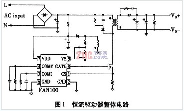
FANl00 Description: 1 pin is the analog input, current detection, the peak current mode connected to the current sense resistor controls the constant voltage mode, and the current detection signal also provides the CC mode of the output current regulation. 2, 6 feet are the grounding terminal. Pin 3 is the analog output. 4 feet for analog output, voltage compensation. Pin 5 is an analog input, voltage terminal. Pin 7 is the voltage reference. Pin 8 is the drive power output.
Working process: Frequency hopping PWM mode of operation, using minimal filtering components for EMI problem methods. The VDD pin (pin 7) is equipped with overvoltage protection and undervoltage lockout, pulse current limiting of the pulse and CC control to ensure overcurrent protection. The gate output is clamped at 15 V to protect the external MOSFET from overvoltage damage, and the internal overtemperature protection function is turned off and overheated when the controller is latched. The startup current is 10μA and the low startup current allows for a startup supply with a high resistance and low startup resistance power supply controller. A 1.5 MΩ, 0.25 W start-up resistor, 10μF/25 V is an AC to DC power adapter with a wide input range (100VAC to 240VAC). The FANl00 built-in provides better temperature compensation for constant temperature regulation in different environments. This internal compensation current is a positive temperature coefficient (PTC) current that compensates for the temperature change of the forward voltage drop diode. This change causes the output voltage temperature to rise.
The sensor senses the entire current sense resistor voltage for current mode control and the pulse is used to limit the current by the pulse. The slope compensation built-in improves stability and prevents subharmonic oscillations due to peak current mode control. The FANl00 has a synchronous, active, tilted ramp built into each switching cycle.
The BiCMOS process of the FANl00 output stage is a fast gate driver. Minimize heat dissipation, increase efficiency, and increase reliability. The output driver is internally clamped with a 15 V Zener diode to protect the power MOSFET transistor from unwanted overvoltage gate signals.
Overvoltage protection prevents damage caused by excessive overvoltage conditions. When the voltage exceeds 28 V, due to abnormal conditions, the PWM pulse drops below the UVLO voltage, disabled until it is below 28 V, then restarts. Overvoltage conditions are usually due to an open feedback loop.
1.3 Experimental Simulation
The experimental simulation voltage input and output relationship is shown in Figure 2. The vertical axis is the output and the horizontal axis is the temperature change. As can be seen from Figure 2, when the input voltage is between 15 V and 17 V, it can be seen that when the temperature rises. At the time, the voltage output is decreasing, so the circuit has a wide temperature fluctuation range.
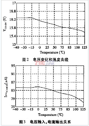
Figure 3 shows the relationship between current input and temperature. When the input current of the circuit is between 75 and 95, the output current fluctuates relatively small. Under such circumstances, the service life of the LED can be prolonged.
2 Summary
The system can extend the service life of the LED and maintain the stability of the output voltage and current within a relatively large temperature fluctuation range. In this way, the DC-DC converter from the battery to the LED can gradually increase the power supply voltage to the forward voltage of the standard LED, and gradually reduce the power supply voltage to the forward voltage, and can keep the current of the LED unchanged (for Constant brightness). At the same time, when the overall input current is higher, a larger inductance is required, and a smaller ripple current is required to limit the peak switching current below the maximum rated current of the IC.
High quality Brigelux & Osran LED chips ,aerospace aluminum housing ,standard IP65 protection ,tempered glass mask. provide single color, RGB, RGBW solution.Can work with DMX 512, DALI system. Project quality,Acceptable price
Classify:Construcion light/Commercial light/City lighting project/Industrial lighting/Urban light.
Install in pool,swimming pool,lake view lighting, musical fountain and city landscape etc.
Hotel Exterior Lighting Project.Hotel design lighting.Hotel Outdoor Lighting.Hotel Landscape Lighting
SHENGYA LIGHTING TECHNOLOGY CO., LTD. , https://www.syalighting.com