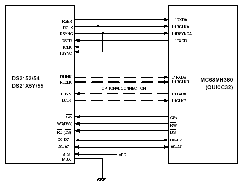
OverviewInterconnections between the DS2152, DS2154, DS21x5Y, or DS2155 and the Motorola MC68MH360 (QUICC32) are shown in Figure 1. The MC68MH360 can be configured as an HDLC controller implementing protocols such as LAPD for T1 FDL, DS0 channel SS7, or the E1 Sa bits.
However, the DS2152, DS21x52 and DS2155 have a built-in HDLC controller for the T1 FDL. Any combination of the QUICC32's SCCs and SMCs can be processed through an internal timeslot assignor onto one or two time-division multiplex channels, TDMA and TDMB. In the configuration shown, TDM channel A is used for timeslots 0 to 23 (T1) or 0 to 31 (E1), and TDM channel B is used optionally for the Sa bit (E1). Refer to the MC68360 Quad Integrated Communications Controller User's Manual for complete details.

Figure 1. DS2152, DS2154, DS21x5Y, or DS2155–QUICC32 Interconnections.
DS2152, DS2154, DS21x5Y, and DS2155 Notes: Other signals affecting operation of device are not shown. Example circuit has RSYNC in output mode. MC68360 Notes: Other signals affecting operation of device are not shown. Use SI mode register t Set up transmit and receive frame-sync delays (0 to 3 clocks) to mask the F-bit in T1 applications. Set clock edges for transmit on rising edge and receive on falling edge. CEA = CEB = 0. In the above example, TDM channel A has a common transmit / receive clock and sync. CTRA = 1. Use the TIMESLOT ASSIGNER to ignore Timeslot 0 for E1 mode.
A DC motor is any of a class of rotary electrical machines that converts direct current electrical energy into mechanical energy. The most common types rely on the forces produced by magnetic fields. Nearly all types of DC motors have some internal mechanism, either electromechanical or electronic, to periodically change the direction of current flow in part of the motor.
DC motors were the first form of motor widely used, as they could be powered from existing direct-current lighting power distribution systems. A DC motor's speed can be controlled over a wide range, using either a variable supply voltage or by changing the strength of current in its field windings. Small DC motors are used in tools, toys, and appliances. The universal motor can operate on direct current but is a lightweight brushed motor used for portable power tools and appliances. Larger DC motors are currently used in propulsion of electric vehicles, elevator and hoists, and in drives for steel rolling mills. The advent of power electronics has made replacement of DC motors with AC motors possible in many applications.
DC Gear Motor,DC Shunt Motor,Shunt Motor,Small DC Motor
Shenzhen Maintex Intelligent Control Co., Ltd. , https://www.maintexmotor.com