Keywords: CPLD, MAX + Plus â…¡ CAD system, online programming, gunsight radar
1 Introduction When designing an electronic jamming trainer for gunsight radar, the entire system requires many integrated circuits such as decoders, latches, buffers, multiplexers, and logic gates, although traditional digital integrated circuits can also be used. The required functions, but there are many problems such as many chips required, large PCB area, poor system stability, inflexible development, and long design cycle. Altera's CPLD (Complex Programmable Logic Device) series products have the advantages of high performance, high integration, in-system programming and short design cycle, and are now common choices for digital circuit design. Altera provides many series of general PLD products such as FLEX10K / 6000/8000, MAX5000 / 7000/9000, and most devices can realize ISP (online programming) through the 4-pin JTAG interface. In addition, Altera ’s CPLD is supported by the MAX + PLUSⅡ development system. It is a single integrated software package that provides design inputs from circuit diagrams, text, and waveforms, to perform compilation, logic synthesis, simulation and timing analysis, and device programming. It is very convenient and flexible to use.
2 System design principle and block diagram
2.1 Device selection The digital logic circuit part of the interference trainer and CPLD has a total of 18 input lines and 34 output lines. Considering the 4 wires of the JTAG interface, special pins such as power and ground, and a certain margin, the MAX7000S is selected The EPM7128S in the 84-pin PLCC package in the series is more suitable. EPM7128S is a CPLD with 2500 gates, 128 micro-macro cells, and 8 logic array blocks.
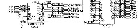
2.2 The basic idea is to set the entire interference training device to 80C196 microcontroller as the core. The parts that need to be completed by the digital logic circuit in the system are: the separation of the low 8-bit data / address; various chip select signals required by EPROM, EEPROM, RAM, 8279 and other chips; the reset signal RST8279 that requires a high-level reset; to be buffered The serial port data communication signals TXD, RXD and permission to send signal TXEN; the address signal and control signal of the electronic switch 4051; the 12-bit digital quantity required by the D / A conversion chip. In addition, taking advantage of the 7128S's online programming, the design deliberately considered several signal lines TCK, TMS, TDI, and TDO required for online programming using the JTAG mode of the download cable ByteBlaster. In this way, the block diagram of the system logic circuit designed with EPM7128S can be shown in Figure 1.


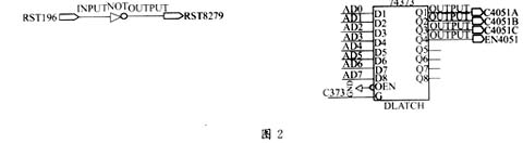
2.3 The definition of internal logic of 7128S According to the above basic idea, the internal logic circuit of 7128S can be designed using MAX + PLUSâ…¡CAD development system as shown in Figure 2.
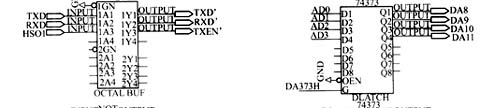
In the circuit of Fig. 2, AD0 ~ AD7 of 80C196 separate the lower 8-bit addresses A0 ~ A7 through 74373, and ALE is used as its address latch enable signal; A13 ~ A15 generate chip select signals such as EPROM, EEPROM and RAM through 74138 and Two strobe signals;
The 8279 chip 4 selection signal is obtained through the first level 74138 and AND gate; the 80C196 low-level reset signal RST196 generates the 8279 reset signal RST8279 via the NOT gate NOT; the system communicates with the host computer (PC) TXD, RXD and permission The transmission signal (HSO1 of 80C196) is buffered and output by 74244; the address control signal required by electronic switch 4051 is generated by AD0 ~ AD7 and address signal C373 by 74373; D / A conversion chip TLV5639 (used to generate interference frequency and intensity) is required The 12-bit digital quantity required for the analog voltage is provided by AD0 ~ AD7 and address signals DA373H and DA373L through two 74373.
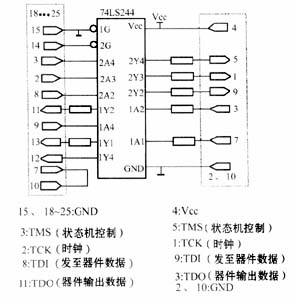
2.4 After the 7128S programming graphic design input is completed, after the pin definition, and then compiled, the device can be programmed. We chose the JTAG mode of the ByteBlaster parallel download cable for online programming. The ByteBlaster download cable includes a 25-pin male socket head connected to the PC parallel port, a 10-pin plug connected to the PCB board, and a 25-pin to 10-pin data conversion circuit. Figure 3 is the data conversion circuit of ByteBlaster.
When programming, first select the device EPM7128SLC84 in the Device item in the Assign menu, use the bottom plan editor (FloorplanEditor) to allocate the device pins and logic units, and use the compiler (Compiler) to the file in Figure 2 (* .gdf ) Compile to generate the programming target file (* .pof) for MAX devices; then use the parallel port download cable ByteBlaster to connect the parallel port of the microcomputer and the PCB board socket with EPM7128SLC84; then select Hardware Setup in the Option menu, and Hardware Setup appears After the window, select ByteBlaster in the Hardware Type box, specify the parallel port (LPT1), and press the OK button. Finally, select Programmer in the MAX + PLUS II menu to open the programmer window and click the Program button to complete the programming of the device EPM7128SLC84.
3 Conclusion In the design of the electronic interference simulation training device, the 7128S device is used, and with the help of MAX + PLUS II software, not only reduces the size of the PCB board, improves the reliability of the entire system, but also in the flexibility of circuit design and shorten the product design cycle Also very advantageous. As a new generation of gun-to-sight radar electronic interference simulation training device, the training device has been used in an anti-aircraft unit, and the effect is very satisfactory.
references
The function of Led Diving Flashlight has 1-5 modes, easy to change according to your situation where you stay at.
LED Diving Flashlight usually high power and super bright, when you go to dive, the brightest flashlight adapt for you.
The products are waterproof, shockproof and tactical, so you need not to worry about its quality.
Most of the products are simple on/off push button operation;
By the way, our products are saled with factory price, and the quality can guarantee, lastly we provide warranty for 1 year;
LED Diving Flashlight
High Power Led Flashlight,Rechargeable Led Flashlight,Zoomable Led Flashlight,Led Diving Flashlight
Ningbo Henglang Import & Export Co.,Ltd , https://www.odistarflashlight.com