Nano's idea began in the summer of 2013, when it was also called "yolk". The idea at the time was to make an entry-level self-balancing car (because of catching up with the school's Freescale game, the balance group was reported at the time. ), the initial idea is: based on Arduino production, you can use the PS2 controller remote control, can balance and walk, it is best to sell Meng.
In fact, that was the first time I contacted and used Arduino. At that time, the teenager was poor... I bought a piece of homemade mini pro bare board, I feel a little happy, and then it was not long before I was connected to the power supply to Huo Huo...
The original version of the egg yolk was made with mini pro. Since there was no 3D printer available for dispatch at the time, all the parts were connected by a versatile all-purpose glue. The overall structure is very rough. How can this be steampunk? (not).
The information on the egg yolk caused a lot of attention after the forum. Many students were smoothly brought into the pit of the self-balancing car... More than a year later, people were asked about related issues, and because of this, they were ashamed to rely on this. The dry goods have been used for a long time, and the individual has a deeper understanding of the self-balancing system... So I decided to improve the many deficiencies of the original egg yolk and set out to design the 2.0 version of the egg yolk.
The dissatisfaction of the first generation is mainly concentrated in the appearance (after all, the value of the face is combat power), speed control (there is almost no speed loop at the time, can only rely on continuous manual adjustment of the balance point to move), scalability (the first generation of peripherals is too simple , did not fully play the performance of the processor), as well as the appearance (can be seen I really care about ...).
Finally, there is Nano~
————————————————————————————————————–
Well, let's take a look at a detailed tutorial on making a Nano, including some on the principles of automatic control and some of the problems and experience that individuals have encountered. It is also worth noting that the complete control of the self-balancing robot requires a large number of parameter debugging processes. Therefore, this tutorial will try to introduce the principle and debugging method in a common way, but you still need to have a certain electronic production basis and familiar with the use of Arduino. , strong hands-on ability, and a strong spirit of geek, I wish success:-)
#原ç†ç¯‡
The self-balancing trolley is a typical inverted pendulum control model. What is an inverted pendulum? The ordinary pendulum is believed to have been seen by everyone.
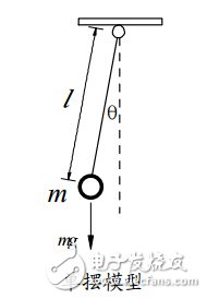
When the object leaves the vertical equilibrium position, it will be combined with the action of gravity and the suspension line to drive the weight back to the equilibrium position. This force is called the restoring force and its size is
F = −mgsinθ
In the case where the offset angle θ is small, sin θ ≈ θ , so the magnitude of the restoring force and the angle of the offset are proportional to each other, and the direction is opposite. Under this restoring force, the single pendulum performs periodic motion.
Considering the pendulum that moves in the air, the pendulum will eventually stop in the vertical equilibrium position due to the damping force of the air. The damping force of the air is proportional to the angular velocity of the pendulum motion and in the opposite direction. The greater the damping force, the more the single pendulum will stabilize in the vertical position as soon as possible.
Now look at such an equivalent model
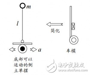
Our car model is actually equivalent to an inverted pendulum. It can be seen that gravity acts downward on the object at this time, that is, when the object is offset by a little angle, the gravity will be the same as the offset angle. If the wheel does not move, the pendulum will fall down quickly.
In order to solve this problem, the inverted pendulum can be stabilized in a vertical position like a pendulum. We have two ways: (1) changing the direction of gravity (2) adding additional force, so that the restoring force is opposite to the direction of displacement.
Obviously only the second method can be done. For this reason, we control the acceleration and deceleration of the wheel according to the offset angle of the pendulum, so that in the coordinate system of the car (non-inertial system), the pendulum will be subjected to additional inertial force, and finally Let the pendulum balance.
To put it more bluntly, when we find that the car is going forward, we will let its wheels accelerate forward. When we find that the car is falling backwards, we will quickly accelerate its wheels backwards, as long as the process is accurate enough and fast. The self-balancing of the car can be achieved.
#硬件篇
The principle says that we need to control the acceleration and deceleration of the wheel according to the angle of the car offset. Then the modules that need to be used according to the requirements are:
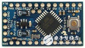
Arduino main control board - choose any piece you are familiar with, recommend nano, compact, easy to download
Gyro accelerometer module - used to measure the tilt angle, recommended MPU6050, cheap, easy to use
Geared motor - the size is self-determined, but the final output speed is about 300rpm. It is worth noting that the motor must be equipped with an encoder or a code wheel for speed measurement. Single or two phase can be used.
Motor drive - TB6612 driver chip is recommended for ordinary size motors. It is more efficient than L298 and is not hot (average current is about 1.2A, power is larger, please choose L298 or other driver); Mini motor can use L9110s module, cheap and compact
Bluetooth module - for communication with mobile phones, from module or master-slave
Buttons - any two-pin button can be used to make some settings
Battery — If it is powered by lithium battery above 5V, it can be used directly, but if the mini car is powered by a small 3.7v battery, you need to pay extra to add a DC boost module, otherwise the Arduino may not work properly at 16MHz.
Additional extended modules can have:
Ultrasonic module - can be used for ranging and obstacle avoidance, SR04 is more commonly used, and the smaller one is RCW-0001. Of course, it is smaller and you can buy and send your own DIY.
Distance sensor - Sharp's range of sensors is more expensive than the ultrasound module, but the effect is better
OLED display - used to display status data, of course, the screen, 0.96-inch resolution 128 × 64 effect is very good, pay attention to the best buy SPI interface, because I2C may conflict with MPU6050 (may be an example, it is reasonable to say that the address is not Conflict, the specific reasons have not been studied)
Buzzer - Let the car sound, it is better than staring at an LED. It is recommended to use an active buzzer.
Camera - Accurately speaking, the infrared light sensor cannot be used because the performance of the Arduino is insufficient for image processing.
In addition to the general welding tools and hand tools, a hot melt glue gun will become your DIY's right hand. As for the structural parts, students with 3D printers can directly download the back STL files to print by themselves. Students without printers can also find the 3D printing service store on the omnipotent orange website. Another point to note is that the small motor I used at the time was modified by myself. It was originally a zoom camera for a digital camera, so it was very compact and could be loaded with a code plate. After changing the reduction ratio and increasing the output shaft, I used it. The car is gone, but now it seems that there is no such thing to sell...
However, I didn't intend to find a more suitable N20 small-speed motor. The performance is much better than the one I modified. The virtual position and friction loss will be better. The shaft can also be directly connected to the wheel, and it is equipped with Hall speed measurement. :
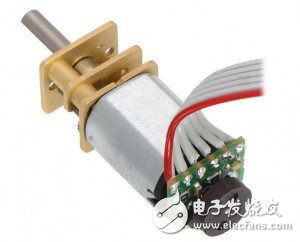
Students who are interested in making ultra-mini balance cars can choose this. TB link will not be sent... Orange net search "N20 gear motor mini" can be found
#软件篇
The software article mainly introduces the PID algorithm. It can be said that the PID is the core of the whole project program. The quality of its use determines whether your car can be self-balancing and the balance is stable and unstable. There are many introductions on the algorithm and theoretical analysis of PID. There is no detailed explanation here. You can search for it yourself. The introduction based on the mathematical model is a bit difficult to understand. This article briefly explains the PID and its usage from the perspective of control.
The so-called PID is the English abbreviation of proportional-integral-differential, but it is not necessary to have these three algorithms at the same time. It can also be PD, PI, or even only P algorithm control. The meaning of each parameter is introduced below:
The first thing to be clear is that to implement the PID algorithm, you must have closed-loop control on the hardware, that is, you must have feedback. For example, to control the speed of a motor, you must have a sensor that measures the speed and feed the result back to the controller. In the self-balancing system, there are three control loops commonly used - angle loop, speed loop, steering loop
Can you imagine what each closed-loop feedback component is? The IMU (gyroscope + accelerometer), encoder, camera (or other identifiable components such as gyroscope, magnetic field meter) included in the above component list. Wait)
P (proportion): Take the car tour line as an example. Now it is necessary to let the car follow a track, use the PID algorithm to control the direction ring, and the feedback sensor is assumed to be the camera. Then there are several situations in the car travel:
1. The car finds itself on the left side of the trajectory through the camera, and the position error value is positive, then it needs to turn to the right, the steering value is positive
2. The car finds itself on the right side of the trajectory through the camera, and the position error value is negative, then it needs to turn to the right, and the steering value is negative.
3. The car finds itself in the middle of the trajectory through the camera, the position error value is 0, very cheerfully straight ahead, the steering value is 0
So we found that the output of the car steering value can be obtained simply by multiplying the position error by a coefficient, and obviously, the larger the error, the larger the steering value obtained, which meets the demand. The coefficient inside is P, and the specific size of the coefficient needs to be determined according to the actual situation.
We have the first formula: P_term = kP * error
D (differential): Take the car tour line as an example, it is still the ratio of the car line. Then there are several situations in the car travel:
Under the influence of P parameters
1. The car gradually closes from the left to the middle, and finally it reaches the midpoint... However, due to inertia, it can't stop! So the car went to the right of the line again.
2. The car gradually closes from the right to the middle, and finally it reaches the midpoint... However, due to inertia, it can't stop! So the car went to the left of the line again.
...
This is not the same as saying good! So at this time D appeared, think about the effect we are expecting is å•¥, we hope that the car reaches the midpoint, at this time not only the position error is 0, but also the steering speed error is also 0.
Then we set the desired steering speed to 0. At this time, if the steering speed of the car is to the right, the error is +, and the left is -
Looking at the previous situation 1, the steering speed error of the car is +, we should give it a leftward steering force in addition to P, to ensure that it will not be so fast when it reaches the midpoint; situation 2 is similar, this Need steering force to the right
In other words, D is equivalent to giving the car a steering resistance, and this force can be obtained by simply multiplying the steering speed error by a factor. Obviously, the greater the steering speed error, the greater the resistance obtained. Demand (note that the steering speed here is relative to the midpoint, not the steering speed of the car output, can be understood as "the speed of position change")
We have the second formula: D_term = kD* (error- last_error)
If the above example is still not easy to understand, consider the previous single pendulum model: P is equivalent to the effect of gravity, allowing the pendulum to reciprocate left and right, while D is equivalent to air resistance, allowing the pendulum to slowly stop at the midpoint. When the size of D is very good, it should be about swinging around and then stopping at the midpoint. Imagine swinging in the water.
I (point)
Sometimes we will find that there are some fixed resistances in the system. For example, we use PID to control the speed of a motor. When the given target speed is small, this will happen:
According to P_term = kP * error, since the error is small, the output of P is also small, and due to the existence of friction, the motor cannot be rotated at this time; and by D_term = kD* (error-last_error), since the motor does not Rotate, obviously (error-last_error) is always 0 and the D output is also 0, then the problem comes, unless the target value is changed, the motor will never turn up...
The role of I is to eliminate such static errors, which will accumulate each error, and then multiply by a factor as an output. For example, in the above case, although the error is small, it is not 0, so in each round of calculation, the I term gradually accumulates the error until the critical value is exceeded to let the motor turn; and in the case of the error of 0, I The item will not help.
The third formula: I_term = kI*(I_term + error)
The above is all the calculation of the PID, and the last three are added together:
PID_output = P_term + I_term + D_term
Run it once every fixed time, which is the PID algorithm.
It can be seen that the algorithm implementation of PID is actually very simple, but only a few lines of code, so it is very recommended to implement the PID code once. There is also a PID library on the Arduino platform, but the name of the library is not what I tell you, go find it yourself.
#åˆ¶é€ ç¯‡
If the above can be understood, you can start making it. Here, the Nano production process will be taken as an example, but you can adjust it according to the actual situation.
The network disk always fails the link, all the files (source code + STL model file + APP) are sent to the non-circuit city (receive 1 yuan when asked me to eat spicy bar...)
The price may still be reviewed, and you need to download it later.
Explain the file inside:
The STL file is the structural part of the Nano head and the body. The base needs to be determined by the different motors. You can make a base with two motors according to the condition of the motor you bought. The help of the hot melt glue gun should be quite simple. of
The source code is recommended to be compiled with the 1.6.5 version of the IDE. The old version of the library file has some differences.
First look at the schematic (click to open the big picture)

It should be noted that the power cord in the figure is not connected (one positive and one negative is known to everyone), and IO can exchange it by itself, as long as the macro definition is changed in the program; the encoder is divided into single phase and AB phase. I use a single phase here, only the speed can not be measured, so the direction of the detection is analogous to the PWM direction of the motor, if it is conditional, it is better to use two-way. For single-phase encoder, connect the signal line directly to D2 and D3, which belong to interrupt 0 and interrupt 1 respectively. If AB phase is connected to D2 or D3, another line is connected to a normal IO to judge the direction. (This time you need to modify the contents of the ENCODER_L() and ENCODER_R() functions at the end of the program).
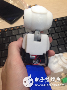
Then start connecting the module to the shell as shown.
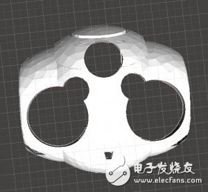
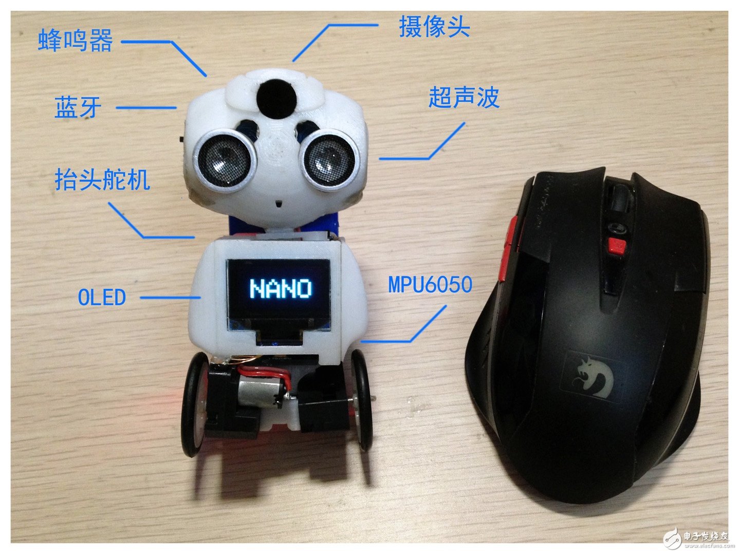
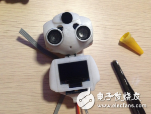
After the document is printed, the schematic is combined. The head is equipped with ultrasonic, Arduino nano board (without pin), Bluetooth module, two LEDs, camera and buzzer. Pay attention to all the IO leads to the neck. Part
Positive look
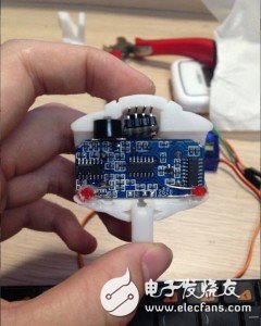
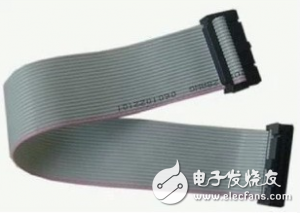
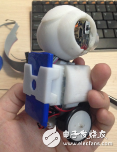
Do not rush to bond the head module after plugging. Then the body wire should be connected to the main control board. The inner parts can be fixed with hot melt adhesive first. For the choice of wire, if the technology is good, you can use the enameled wire to save the most space. If you are not sure, use this FC cable. It is easier to soften and peel. It is finer and the whole row will be beautiful. DuPont line is really not. Easy to use...
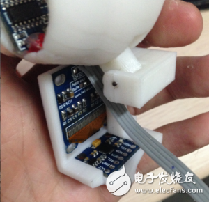
The main part of the body is the steering gear (if you want to use), OLED, motor drive board and booster board, OLED plug, please do not use brute force or screen glass is fragile (don't ask how I know...)
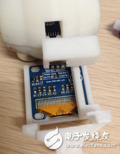
If the lead is pulled out when the head is mounted, it can be soldered to the screen.
MPU6050 is at the bottom and is also fixed with 502 or hot melt adhesive.
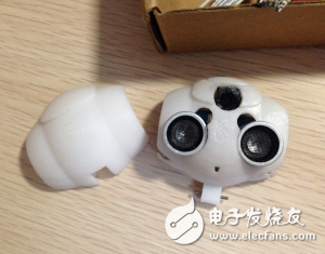
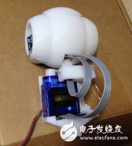
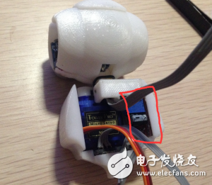
Then there is the steering gear. The steering gear is the most common 9g steering gear. Although it is smaller but not enough torque, you can see that the connecting rod that pushes the neck by the steering arm of the steering gear can make the head move. The steering gear is not recommended. One is that the battery power of the small robot is relatively small. When the steering gear is locked, it is easy to cause a crash. The weight of the other head is relatively large, so the change of the center of gravity during movement is easy to interfere with the balance. Will be more complicated
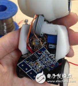
Then install the side of the body part, first fix the booster plate to one side with hot melt adhesive, then cover the cover with 502 (red circle is a DC-DC booster plate)
At this time, the subject is almost finished.
At this time, the motor base can be started. One reference scheme is to cut the substrate with a discarded telephone card or bank card, and then fix the two motors to the substrate with hot melt glue, so that the substrate can be glued and body. Bonded up
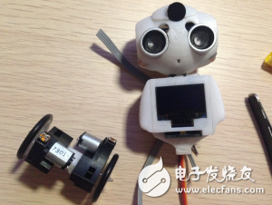
Now I can install the motor drive, I use the L9110S, directly on the back of the body
Finishing the entire body part of the back cover is complete
Finally, the battery pack, find a lighter battery directly on the back, you can also add a battery cover
Side look
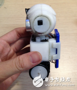
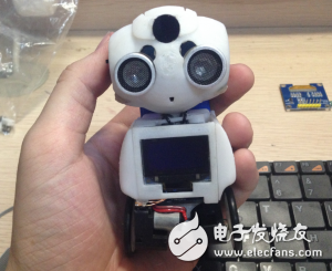
The little Nano is done!
Of course, it will not move now. At this time, don't rush to glue the head. First, write a few small programs to test the working status of each module one by one. For example, whether the ultrasound works, 6050 has no data, these programs are directly Go to each library and find the routine to change the defined pin to see the effect.
When it is determined that there is no problem, carefully fix each part with hot melt adhesive and prepare to start the program debugging work.
Open any file in the source folder, you can see the entire project code
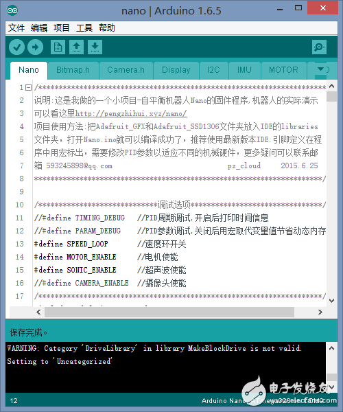
The first thing that needs to be modified is the pin definition, which changes the pin to your actual connection.
/********************* Pin definitions*********************/
#define LFT 0
#define RHT 1
#define BUZZER 4 //Buzzer
#define BUTTON 5 // button
#define LED 11 //Cheek LED
//#define SERVO 13 //Steering gear, small robot is not recommended, current is easy to overload
#define TRIG_PIN 8 //Ultrasonic module trigger pin
#define ECHO_PIN 7 //Ultrasonic module receiving foot
Then in the top debug option, uncomment the IMU_OUTPUT, like this
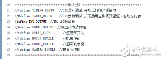
Download the program to the main control, open the serial monitor, press the button, you can see the output angle data.
If the data is not normal, you need to check what went wrong in front of you. This step is to get the natural angle of the robot balance: manually put the robot right, it is about the balance angle of the natural center of gravity, read the angle data of the serial port, record this value Is the value of angle_setpoint, change the angle_setpoint = 0 of 66 lines to the value you get.
Next, re-comment the IMU_OUTPUT, open the MOTOR_ENABLE comment, and then use the Motor (char LR, int SPEED) function to check the positive and negative polarity of the motor at the end of the setup(), that is, when giving the Motor (LFT) When 100), the left wheel rotates forward, the Motor (LFT, -100) reverses the left wheel, the Motor (RHT, 100) rotates the right wheel, and the Motor (RHT, -100) reverses the right wheel.
After the previous step is also detected successfully, you can start to adjust the PID parameters of the angle ring.
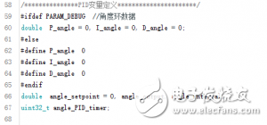
Explain that the reason for defining the parameters with macros is that if the mega328p chip is used, the amount of the entire program code is still quite large, so the dynamic memory will be prompted, so after the parameters are debugged, they are solidified with macros. SRAM
The overall parameter tuning principle is:
First P and D, if the motor response is slow (such as a motor with a lot of deceleration), then adjust I, if the PD effect is good enough, then I do not need
Single variable method, that is, when adjusting one parameter, other parameters are fixed.
First, quantify the value again. For example, when adjusting P, start with 0.0001, check the car reaction. If there is no effect, change it to 0.001, and so on, until you determine an appropriate order of magnitude, then start fine-tuning in this order. In fact, the scope of the adjustment has been reduced to a small
First overshoot and then reduce, that is, all parameters should be increased as much as possible until the system oscillates, and then take the smaller value of this value as the most suitable parameter.
Try to keep the car in a natural state during the debugging process without additional force, that is, try to use wireless debugging, if you are wired, find a softer line.
Well, what is the performance of the car in the adjustment process?
In the angle ring, when P gradually increases, the car will begin to have a resilience effect, that is, when the hand is held forward, the car can also follow the move, but it is still very soft, and then gradually Increasing the parameters, the resilience is getting bigger and bigger, until it reaches a certain level, the car starts to violently shake before and after, and the car with better motor performance can stand up even if the hand is not supported.
Slightly reduce the parameters that have just oscillated. As the P value is fixed in the program, the D value is adjusted. It is still gradually increased after the magnitude is determined. During the process of increasing, the oscillation frequency of the car will gradually decrease and increase to A certain degree of car basically no longer oscillates, this value is the required D value.
In some cases, due to motor performance reasons, the above PD can not achieve good results during the adjustment process. Then I need to add I. After adjusting the P value, the D value is set to 0, and the I value is increased until the car is The resilience becomes "hard", then slightly decrease the P value until the ideal erect effect occurs; finally add D, the effect increases until the shock, and then decreases to about 70%, so that all parameters of the angle ring PID The tuning is complete.
The angle is adjusted, the car can be balanced, but why is it running all the way?
Because the angle loop's task is to maintain the angle of the car, in addition to its ability range, the angle ring does not care whether the car is stationary or balanced, or balance while running - if the target balance point and car center of gravity The balance points coincide, so the car can be stationary, and if not, the car will accelerate in the balance until the speed of the wheel exceeds the speed that the motor can provide, so the car will still fall.
So we need to add a speed loop and measure the speed with the encoder as feedback.
In the speed loop, first determine that the value obtained by the encoder is correct. In the program, count_L and count_R store the count respectively. If you print the output, turn the wheel to see the data. If it is correct, on the basis of adjusting the angle loop, You can add a speed loop.
Cancel the comment of SPEED_LOOP in the debugging options, then we don't need D this time, the speed loop is adjusted by PI alone, and I adjust P first, the corresponding performance is as follows:
First give a relatively small P value (because I is the accumulation of P, if P is 0, I will have no meaning), as the value of I gradually increases, push the car by hand, the car will move forward and then slowly retreat. It means that the parameters are working. At this point you can decide whether to give a larger I value or a smaller I value. The larger I value corresponds to a faster recovery speed, and after the deviation, it will retreat more violently and return to the origin within a shorter distance. However, of course, this will also reduce the stability of the car, while the small parameters are the opposite. It needs to go back to the origin after moving a longer distance, but it also makes the anti-interference ability stronger, that is, it will not be Easy to push down.
Only use the I value, then the car's reply will be reciprocating, gradually approaching the origin, plus the P value can eliminate this back and forth oscillation, as the angle ring adjusts the D value, gradually increase until the push can be swung back and forth Returning to the origin at rest once, this P value is the most appropriate parameter corresponding to that I value.
Here is a video of the anti-jamming of a big car I used to do. The motor performance of this car is very violent, so you can see that its balance performance is very good.
The adjustment process of the PID parameters is probably the same. In short, this is a work that requires careful adjustment but a high degree of freedom. The so-called "bold assumptions, careful verification", after trying several combinations of parameters, you will find the right one for you. The magic point of the car~
There are still many things to say about the adjustment of the parameters. For example, in the form of adjustment, you can add several potentiometers to the trolley and use analogRead to read them as parameter values. This makes it easy and intuitive to observe the continuous changes of parameters. The impact of; for example, wireless debugging, using the serial port protocol control of the SSH terminal will be much more convenient than using the serial port assistant. But I think the most effective way to understand the parameters is to operate it by hand. Try more comparisons. There is also a more detailed parameter tuning video tutorial. It is recommended that you continue to watch it. The debugging of the direction ring is also described in detail:
Features Cotton Braided Sleeving
1. Totally expanded the sleeving can reach at least one point five times than the initial dimension.
2. Suitable for constructing and protecting cable harnesses or tidying cable looms.
3. Sleeve expands to allow the cables to pass through and then automatically shrinks back.
4. Multiple sizes and lengths available .
High Density Matte Solid Expandable Braided Cable Sleeving is the best sleeving out there in the market. It is the Tight, High Quality, High Density, Matte, Solid Sleeving which protects and hides wires while increasing air flow.
Cotton braided sleevings are perfect for single small cables. All our extension cables are made with these sleevings. Its ultra tight weave small sleeve. Braided sleevings will go inside any type of connector hole. These sleevings will make your pc look different. You can use it with or without heat shrinks!!
Sleeve any power supply or anything else without worrying of Bleeding issues!
Cotton Braided Sleeve ,Expandable Braided Sleeve,Wire Cable Lot Sleeving Sheathing ,Braided Cotton Sleeve
Shenzhen Huiyunhai Tech.Co.,Ltd , https://www.hyhbraidedsleeve.com