If you want the motor to start, it is not as simple as closing the brake. There is still a lot to be done to achieve remote control and multipoint control. This article lists several of the most basic motor control loops, except for the mechanical control required in production, which are also mandatory when designing PLC circuits.
This article will be explained from easy to difficult.
Motor control loop common components
Button â–¼
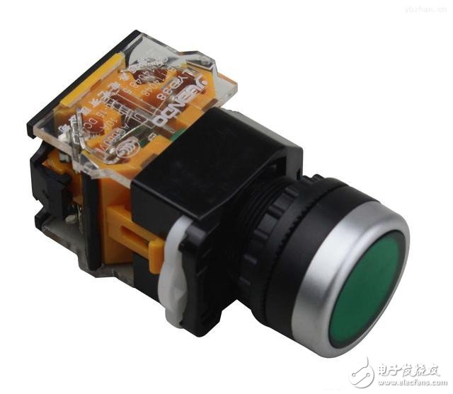
The buttons are divided into a start button, a stop button, and a mechanical interlock button. The first two have a total of 4 posts, the latter has 6 posts.
The start button is mostly green, and the internal is normally disconnected. After pressing the button, the inside is closed, and then released and then disconnected;
The stop button is mostly red, and the interior is normally closed. After the button is pressed, the interior is disconnected, and then released and closed.
The mechanical interlock button can be regarded as a double-throw switch with a total of 6 binding posts. Usually the left terminal is connected. After pressing, the right terminal is connected. After the release, the left terminal is connected. As a start button or stop button.
The button is generally indicated by SB. If there are multiple buttons at the same time, the number will be added after the SB, such as SB1, SB2.
Contactor / Relay â–¼
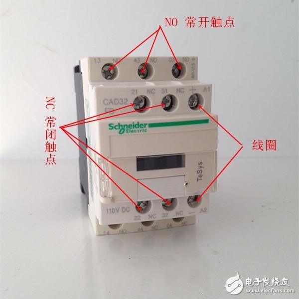
The figure above is the contactor, the relay is small compared to it, but the principle is the same. There are a total of 12 binding posts in two rows (2 binding posts, one into one and one out). In the top row of terminals, there are 2 sets of normally closed contacts, and 1 set of coil contacts, and the lower row has 3 sets of normally open contacts.
Working characteristics: When the coil is not energized, the normally closed contact is closed and the normally open contact is opened; after the coil is energized, the normally closed contact is opened and the normally open contact is closed.
Contactors, regardless of which contact or coil, are indicated by KM. If there are multiple contactors, add numbers after KM, such as KM1, KM2. All contacts and coils of the same contactor are marked with a set of numbers, such as the normally open contact of the contactor KM1, the normally closed contact and the coil. The marks in the circuit diagram are all KM1.
Jog and linkage
Jog: The motor starts when the button is pressed, and the motor stops when released.
Linkage: The motor starts when the button is pressed, and the motor continues to run after the release.
Circuit â–¼
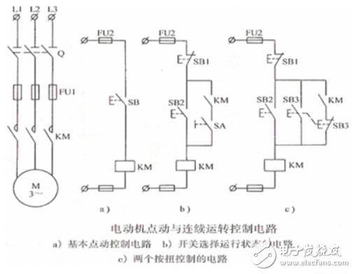
In the above figure, the left side is the main loop, and the right side a, b, and c are three different control loops.
In Figure a, the button SB is pressed and the motor is started. After the release, the motor stops. It is a typical jog control.
In Figure b, when the circuit breaker SA is disconnected, the button SB2 is pressed, the contactor coil KM is energized, the normally open contact KM is closed, but there is a circuit breaker under the normally open contact KM to disconnect it, so although the motor is now Start, but it will stop after being released. After the circuit breaker SA is closed, the button SB2 is pressed, and the contactor coil KM is energized. At this time, the normally open contact KM is closed, so that after the SB2 is released, the motor can still operate normally. At this point the motor is linked. Therefore, this diagram can manually control the jog or interlock state.
In Figure c, there is no circuit breaker, instead a mechanical interlock switch SB3. When the button SB2 is pressed, the contactor coil is energized, the normally open contact KM is closed, the motor is started, and after the release, since the normally open contact is still closed, the motor operates normally. When button SB3 is pressed, the button normally closed contact SB3 under the normally open contact of the contactor is opened, and the normally open contact of the button SB3 is closed, the motor is started, and the motor is stopped after being released (the contactor normally open contact is not at this time) Access circuit). Therefore, this circuit can directly press SB3 when the motor is linked, and it becomes jog.
When the motor is interlocked, after the start button is released, the normally open contact KM is closed due to the energization of the contactor coil, and the motor can be continuously operated. This concept is called “self-lockingâ€.
Motor jog and linkage is just a concept, no one wants his own motor to jog. Here we only need to know how to keep the motor running continuously.
Off-site control of the motor
This article takes two places to control the motor as an example. Multiple control of the motor is generally divided into remote control and local control. That is, put the start button into a different button box, and then install the button box at the place to be controlled.
Circuit â–¼
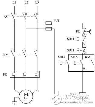
With the knowledge of jog and linkage, the role of the contactor KM in this figure need not be said. In the figure, SB11 and SB21 are stop buttons, and SB12 and SB22 are start buttons. One of the start button and the stop button is installed in the same button box, and the other two are also installed in another button box. Two button boxes can be placed next to the control room and the motor.
Physical connection diagram â–¼
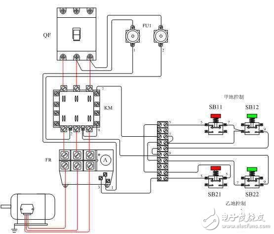
When controlling the motor in different places, you only need to pay attention to the fact that the stop buttons are all connected in series, and the start buttons are all connected in parallel.
Motor sequence starts
The two motors M1, M2 are sequentially activated as an example. M2 is required to start after M1 is started, and M1 can be started separately.
Circuit â–¼
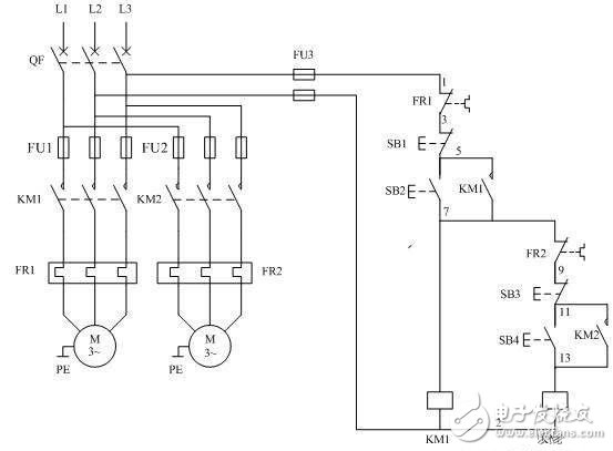
Among them, the buttons SB1 and SB3 are stop buttons for controlling the motors M1 and M2, respectively; the buttons SB2 and SB4 are start buttons for controlling the motors M1 and M2, respectively. For the sake of easy understanding, I highlight the control loop of M2 in the circuit diagram. When the control loop of M2 is mentioned below, it refers to the one protruding from the far right side in the above figure.
Similarly, the role of the contactor will not be described again. As shown in the figure, when M1 is not running, that is, the normally open contact KM1 is not closed, the control circuit of M2 is disconnected at this time, so when the start button SB4 is pressed, M2 does not react. Only when M1 is running normally, KM1 is closed, and the control circuit of M2 is powered. At this time, M2 can start normally.
Physical connection diagram â–¼
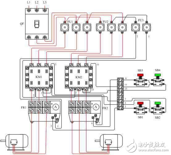
If multiple motors are required to start at the same time, there are two cases:
If other motors are required to start after M1 is started, connect the control loop of the motor to the control loop of M2.
If other motors are required to start after M2 is started, connect the control loop of the motor to the control loop of M2.
Motor reversing
To achieve positive and negative motor rotation, the principle used is to change the phase sequence of the three-phase electricity by using two contactors.
Circuit â–¼
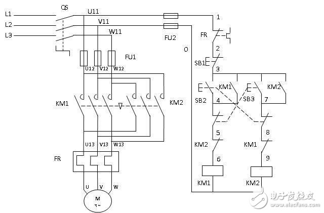
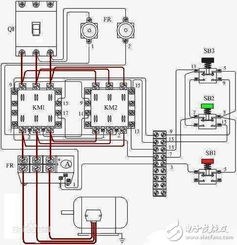
Note that the main circuit on the left side, the order of the three items of electricity L1, L2, L3 reaching the motor M1 through the contactor KM1 is left, center and right; and the order of reaching the motor M1 through the contactor KM2 is right, center and left. The change in phase sequence achieves a change in the direction of operation of the motor. This usage is used in electric vehicles or electric tricycles to achieve the function of reversing. There is now a more convenient component called the "reverse switch", which is the principle.
For convenience of description, it is assumed that the direction of motor rotation is positive when the SB2 loop is closed, and the loop where SB2 is located is the forward loop, and the loop where SB3 is located is the reverse loop.
Let's look at the control loop. For the sake of convenience, we have numbered the numbers in the figure. Each number corresponds to the component directly above it. Similarly, the effect of the contactor normally open coils KM1 and KM2 is not repeated.
This figure is well understood if there are no normally closed contacts for the two contactors numbered 6 and 9 and the normally closed contacts of the two mechanical interlock buttons numbered 5 and 8. That is, when SB2 is pressed, the motor rotates forward, and SB3 is pressed, and the motor is reversed.
There is a problem here that if SB2 and SB3 are pressed at the same time or SB3 is pressed while the motor is rotating forward, a short circuit accident will occur. Therefore, we have connected the contactor normally closed contact in the circuit. The normally closed contact of KM2 is connected to the forward control loop, and the normally closed contact of KM1 is connected to the reversed control loop. Thus, when the motor rotates forward, since the coil of the contactor KM1 is energized, the normally closed contact KM1 is in the off state, so even if the button SB3 is pressed at this time, there is no reaction.
The normally closed contacts of the two contactors are respectively connected to the circuit in which the other party is located, so that when one of the contactors is energized, the other contactor can no longer be energized, which is "interlocking".
At this point we are still facing a trouble, that is, when the motor is rotating forward, if you want to reverse it, the only way is to press the stop button and then press the reverse button, which is very troublesome. For convenience, we used a mechanical interlocking button and connected its normally closed contact to the control loop next to it - number 5 and number 8 in the figure.
At this time, when the motor is rotating forward, we press SB3, then the normally closed contact of number 5 is disconnected, that is, the forward rotation circuit is de-energized, so the coil KM1 is de-energized, and the normally closed contact KM1 is restored to the closed state, the coil KM2 You can get electricity and the reverse loop works normally. In this way, when the motor is rotating forward and reverse, it is no longer necessary to press the stop button again.
Physical connection diagram â–¼
In practical applications, it is often necessary to combine all of the above circuits, but as long as the original ideal of a single figure is understood, there is more knowledge involved, and it is not a problem.
According to the different electrolyte materials used in lithium-ion batteries, lithium-ion batteries are divided into liquid lithium-ion batteries (Liquified Lithium-Ion Battery, referred to as LIB) and polymer lithium-ion batteries (Polymer Lithium-Ion Battery, referred to as PLB) or plastic lithium Ion batteries (Plastic Lithium Ion Batteries, referred to as PLB). The positive and negative materials used in polymer lithium-ion batteries are the same as liquid lithium ions. The positive electrode materials are divided into lithium cobalt oxide, lithium manganate, ternary materials and lithium iron phosphate materials. The negative electrode is graphite, and the working principle of the battery is also basic. Unanimous. The main difference between them lies in the difference in electrolytes. Liquid lithium-ion batteries use liquid electrolytes, while polymer lithium-ion batteries are replaced by solid polymer electrolytes. This polymer can be "dry" or "colloidal." of. Polymer lithium ion batteries have the characteristics of good safety performance, light weight, large capacity and low internal resistance.
Polymer Lithium Ion Battery,Durable Lifepo4 Dadn72V 45Ah,High Performance Batteries For Electric Motorcycles,High Performance 72V Batteries
Shandong Huachuang Times Optoelectronics Technology Co., Ltd. , https://www.dadncell.com