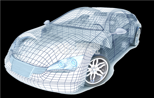
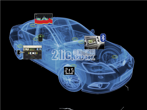
China has become a big country in the use of automobiles, and the safety of cars has become more and more concerned. The root cause is the occurrence of traffic accidents. As one of the three safety systems of the car, the TPMS car tire intelligent monitoring system has been recognized and valued by the public together with the car airbag and anti-lock braking system (ABS). The role of the TPMS (Tire Pressure Monitoring System) is to automatically monitor the tire pressure during real-time driving and to alert the tires to leaks and low air pressure to ensure safe driving.
This article refers to the address: http://
TPMS is one of the important systems for car safety. In 2007, the United States established the FMVSS 138 regulations. Subsequently, the European Union, Japan and ISO have developed corresponding TPMS standards. China also in March 2015, the National Automotive Standardization Technical Committee Automotive Electronics. The mandatory national standard “Performance Requirements and Test Methods for Passenger Car Tire Pressure Monitoring System†drafted by the Technical Committee of Electromagnetic Compatibility has been completed.
Tektronix Technologies is responding to the R&D and production test requirements of TPMS, and has launched a new test solution that meets the requirements. Tektronix' widely used oscilloscopes MDO3000/4000C and MSO5000B can fully satisfy the test analysis of baseband signals and protocol CAN/LIN. The spectrum analyzer MDO4000C and the real-time spectrum RSA306B, RSA603A and RSA5000B can accurately test the parameters of the radio frequency, and the modulation parameters can also be simultaneously Measurement analysis, the unique time-varying analysis features of the real-time signals of the DPX real-time spectrum RSA306B, RSA603A and RSA5000B can also help engineers analyze more product features. The TSG4100A's high-performance analog and vector sources provide good signal generation and sensitivity testing, and the 2450/2461SMU accurately analyzes the power consumption characteristics of TPMS modules. Most importantly, the MDO4000C performs mixed-domain test analysis of baseband and RF, allowing engineers to not only understand baseband data timing, RF parameters, but also to test and analyze the time dependence of baseband and RF.
Tektronix offers you a test solution:
â—¦ KEI2450 source measurement unit accurately measures and records the standby power consumption of TPMS: accurately measures sleep currents less than 10nA
â—¦ RSA306B/603A spectrum analyzer can analyze TPMS
â–ª Accurate 433/315M power and frequency measurements
â–ª Complete frame data analysis with demodulated waveforms
â–ª Unique frame data duration measurement
â–ª Real-time spectrum dynamic time-varying observation
â–ª Power level triggers RF capture for TPMS features
â—¦ RSA306B spectrum analyzer + KEI2450 source measurement unit + TSG4102A vector signal generator is the best test tool for TPMS, cost-effective solution
Tektronix' TPMS test solution can complete the following project tests:
(1) Data timing analysis of baseband signals
Baseband data sequence analysis: It is mainly for the correctness of the data sequence of the TPMS modulation or the data sequence of the receiver demodulation or the deterioration of the waveform, which can ensure the transmission of normal modulation data, and can also be used to verify the sensitivity or solution in the receiver test. To adjust the threshold, if the encoding method is known (such as Manchester encoding), you can also verify the correctness of the encoding.
In a typical TPMS application, the output power of the transmitting module is designed to be the maximum power allowed by the electromagnetic radiation standards specified by government agencies.

Figure 1. Input enable filter is enabled and the input signal and demodulation output are matched to the timing requirements of the filter.
(2) Parameter measurement of radio frequency signals
TPMS module testing mainly includes power and spectrum testing, modulation quality testing, and spurious emissions. The purpose of power and spectrum testing is mainly to verify that the device transmits enough power levels to ensure transmission distance, while having the correct modulation waveform and less spectral interference components.

figure 2
The spectrum of 433.92 captured by the RSA306B analyzer, as shown in the right figure of Figure 2 is the general spectrum display, while the left picture is the spectrum of the DPX display. It can be clearly seen that the right picture captures more times than the left and right spectrum, which is reflected in For the color brightness of the display, for the TPMS, the general spectrum analyzer basically cannot capture the complete RF signal, and the emission spectrum of the TPMS can be easily seen by the 10,000 times per second spectrum capture of the DPX technology.
As shown in FIG. 3, for a frame of data signal transmitted by the TPMS, the long-term spectrum capture of the RSA 306B can completely analyze one frame of data waveform or accurately measure the time of one frame of data.

image 3
(3) Analysis of modulation characteristics of RF signals and RF code demodulation
The modulation of the radio frequency of TPMS generally adopts the method of ASK or FSK. The modulation quality analysis mainly tests the modulation precision, modulation index and other parameters for ASK and FSK digital modulation to ensure that the device has the correct modulation mode, and the modulation index and accuracy meet the requirements. Never affect the quality of communication.
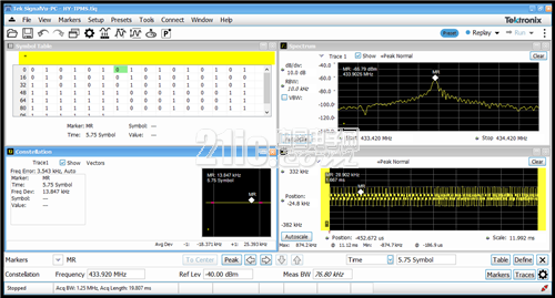
Figure 4. RSA306B signal analyzer simultaneously measures RF power, FSK demodulated data code, FSK demodulation characteristics (parameters) and constellation diagrams.
Engineers can perform a comprehensive RF analysis of the functions of the TPMS to gain a clear understanding of the TPMS features being designed.
(4) Time domain correlation analysis of mixed domain (baseband and radio frequency)
Mixed-domain correlation analysis of baseband and RF signals allows engineers to better understand the system characteristics of the designed product. Engineers can simultaneously capture RF, analog (baseband, control, time base), data (coding), and protocol (CAN/) with the help of the MDO4000C. The LIN/SPI signal can accurately analyze the timing relationship between these signals to prevent softness, occasional non-communication, and unreliability of the product system.
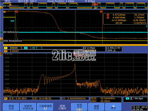
Figure 5. RF signal, chip select signal, RF FSK demodulation waveform, etc. captured simultaneously by MDO4000C
As shown in Figure 5, you can actually add SPI or CAN/LIN protocol signals. This test method allows engineers to more clearly understand the working status of the TPMS, whether it is the baseband data sequence or the RF parameters. The time relationship between the baseband and the radio frequency is very clear. Such an analysis method can reduce the difficulty of designing the TPMS and improve the operational reliability of the TPMS.
A 6 layer PCB board is in general a 4 Layer PCB board with 2 extra signal layers added between the planes. The 6-layer PCB classic stackup includes 4 routing layers (2 outer layers + 2 internal layers) and 2 internal planes (one for ground and the other for power). This enhances the EMI dramatically by offering 2 buried layers for high-speed signals and 2 surface layers for routing low speed signals. The signal layers should be closed to the adjacent planes.
6 layer PCB
Storm Circuit Technology Ltd , https://www.stormpcb.com