For the cost of buck circuits, many people think that the advantages are not obvious compared with the three-stage circuit. But in fact, in terms of performance, size, and reliability, the buck circuit is better than the third-level circuit. Designers entangled in cost issues may have an underestimation because of fewer opportunities for practice and insufficient understanding of costs. On the other hand, once a number of companies start to produce, they will certainly optimize the circuit, and the cost will no longer be a problem. Let's discuss the cost of dual buck circuits.
In terms of performance, the three-level circuit is not at the same level as the double buck. But the three-level circuit control is very simple and easy to understand, unlike the double buck circuit control is complex and accurate. The three-stage circuit uses too many MOS power devices, which affects the reliability of large quantities. This is one of them. The second is the shortcoming of the traditional buck circuit. No matter which working mode, there is no double buck performance. This is one of the reasons for the inefficiency. Most people know. The third is the working characteristics of the three-stage circuit, which causes the interference to be larger than the two-stage.
Take the 70W HID ballast scheme as an example. There are high frequency, three-level full-bridge low-frequency general scheme, and two-stage half-bridge dual buck scheme, all of which are designed successfully. Among them, I want to talk about the two-level and three-level main features of the low-frequency solution: two-stage half-bridge double buck solution: it is not cheaper than the third level in terms of cost. But the performance is better than the third level, such as: output waveform, temperature rise, efficiency and so on. However, the control of the double buck is more complicated, the parameter debugging is troublesome, and it is mutually restrained. When the debugging is slightly inadvertent, it will be loud, but once the parameter debugging is OK, it can run reliably. As for the constant power control accuracy and the overall control of the MCU and the three levels, the constant current method is used to achieve constant power. Three-level full-bridge low-frequency general solution: The circuit structure is clear and easy to understand. Each part operates independently, which is easy to debug. The components are highly versatile and easy to purchase. Resonant ignition can be used, and the ignition MOSFET or IGBT can be omitted relative to the two stages. In order to avoid product homogenization and highlight its differentiation, it is mainly producing two-stage half-bridge double buck structure metal halide lamp electronic ballasts. It is believed that with the increase of output, the component cost will drop to a certain extent. It will be more advantageous than the three-level full-bridge structure.
The efficiency of the third level is actually not a problem. Debugging properly 91 is not a big problem. But the problem is not efficiency here. The problem of reversing aluminum electrolysis is indeed a problem, otherwise CCI will not control such a complicated waveform. But this problem, fundamentally speaking, is solvable, but the control circuit is more complicated. If the three-stage circuit is stepped down to the bus terminal, high-voltage driving is required, and the driving is troublesome. Of course, the result is that sampling is convenient. If it is at the ground, sampling is inconvenient. The whole bridge is uncontrollable.
On the cost, the half-bridge two-level and the full-bridge three levels are difficult to distinguish who is taller and who is lower. On the performance, it is difficult to distinguish between good and bad, each has its own shortcomings. The key is to see who can understand the principle and control the process so that a stable and reliable product can be made. Now, due to the high technical threshold of the metal halide lamp ballast industry, the price is not considered as the main factor. Staying at the level of plagiarism, let alone deep understanding or even improving the level of improvement, although there are few.
Let's restore it to the two topologies of the actual application.

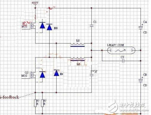
In Figure 2, in order to prevent Q1Q2 from being turned on at the same time (that is, the dead zone), "Tianditong" is caused, and an inductor is added. Even if Q1Q2 is turned on at the same time for a short time, the current will not be abrupt, in three or two microseconds. No harm.
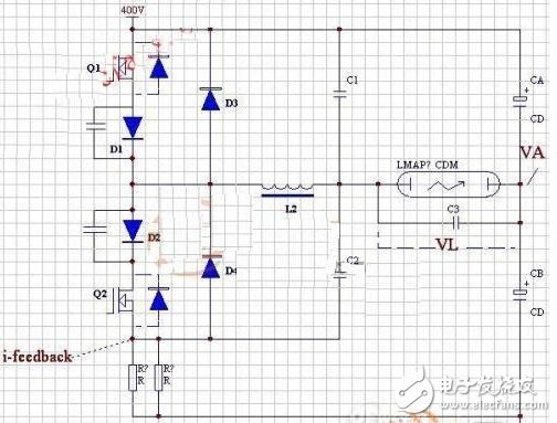
In Figure 3, after fully evaluating its confidence in the dead time control, only one inductor is used; but Q1Q2 is parasitic with a diode in the body and is slow recovery, which will make the parallel D3D4 not work. , slow down, fever. Therefore, the D1D2 low-on-voltage Schottky diode is connected in series, so that D3D4 can separately perform the free-wheeling action in its own phase region.
It can be seen that the relationship of C1C2C3 is parallel. Why? Because CA and CB are far larger than them, C1C2C3 is equivalent to parallel in the state of high-frequency pulse current.
Then talk about the timing, when the commutation, such as: Q1 stop, the turn of Q2 work, when Q2 is open, the pressure drop on L2 is 200V (VA) + VL, slowly transition to 200V (VA) - VL. The current that discharges C2 at this moment does not pass through the current sampling resistor. With the large power, the C2 capacity is also large. When the power is low, it can be supported by Q2. When the power is high, how can the tens of amps of the rush current support? In order to balance the effectiveness of current sampling, C3 is much smaller than C1C2.
The cost of dual buck has unique insights and is compared with the three-level circuit. Finally, we will further analyze the differences through examples. I hope that everyone can gain something after reading this article.
Recommended reading: buck/BOOST circuit principle analysis
VAWT Vertical Axis Wind Turbine
wind turbine system, wind turbine generator system, wind turbine blade, maglev wind turbine, vertical axis wind generator, windmill generator, wind turbine generator types, vertical axis wind turbine, vertical generator wind turbine, vertical wind generator, vertical wind turbine, Wind Power Generator for home, wind turbine generator kit
VAWT Vertical Axis Wind Turbine, VAWT Vertical Windmill Generator,VAWT Vertical Wind Turbine Generator Types, VAWT Vertical Axis Wind Turbine,Vertical Generator Wind Turbine
Delight Eco Energy Supplies Co., Ltd. , https://www.cndelight.com