In the past two years, LCD production has flourished in China. In the past two years, South China has established a number of new factories. Because of the work relationship, it often interacts with many people in the industry. Among them, LCD manufacturers also work in LCM. The factory found that there are many problems in this industry that are plaguing everyone. This paper selects the ESD (ElectricalStaTIcDischarge) problem for analysis, because the defects caused by ESD are generated at any time during the LCD and LCM production process. The main defects are the breakdown of the PI layer by static electricity and the influence of static electricity on the display failure. . This paper focuses on solving the black and white strip defects of STN lattice caused by static electricity, and provides feasible solutions for other electrostatic defects.
In this paper, the cause analysis of ESD is focused on solving the effect of static electricity on the black and white bars of LCD display. At the same time, the problem is verified by experiments. Because my level is limited, some of them may be improper. I hope you understand. I only hope that this article can help technicians in the LCD and LCM industries.
The substances in nature are composed of molecules. The molecules are composed of atoms. The atoms are composed of positively charged electrons and negatively charged protons. In general, the number of electrons in an atom is equal to the number of protons, and the object exhibits an uncharged phenomenon. However, when two different substances are in contact with each other, one object loses electrons positively charged and the other material receives electrons negatively charged. If the charge is difficult to neutralize during the separation process, the object is electrostatically charged.
Second, electrostatic discharge mode (ESD)Because the causes and discharges of ESD vary, the following comprehensive ESD models are available:
1, human body discharge mode (HumanBodyMode)
HBM mode is mainly caused by the friction between the body and clothing or shoes and the ground during the walking process. When the human body is in contact with the IC or LCD device, the static electricity will be introduced into the IC device or the LCD case through the IC pin or the external electrode of the device. .
2, equipment discharge mode (MachineMode)
MM mode is the accumulation of static electricity during the production process of the equipment (such as the automatic transportation process of the glass substrate). When the device contacts the device, if there is a potential difference, ESD will be generated.
3, device charging mode (Charge_DeviceMode)
The CDM mode is that the device itself accumulates static electricity, especially in LCD devices. When both upper and lower glass substrates accumulate static electricity and have a large potential difference, ESD is generated. The CDM mode discharges quickly and causes a large destructive force. The assembled LCD also introduces a large amount of charge into the box during production, and ESD is generated if a proper discharge environment is encountered.
4, electric field sensing mode (Field-InducedMode)
The FIM mode is mainly generated in the LCM process. When an IC passes an electric field, the relative polarity of the charge is released through some pins. When the IC passes through the electric field, it will accumulate some static charge. The electrostatic charge will be released through a CDM-like mode. .
5, test import mode (Test-GuideMode)
The TGM mode is a common mode. During the LCD and LCM test, the relative polarity of the charge enters the box through the pin during the electric field test, causing some electrodes to be charged, affecting the twist of the LC molecules. To display black bars and white bars.
Third, LCD process analysisA basic LCD production process is divided into the following steps:
Glass substrate blue - cleaning - coating photosensitive glue - UV exposure - hard film - etching - stripping - cleaning - TOP coating - PI coating - friction - cleaning - printing frame - printing - boxing - cutting - filling - Splitting-light inspection - electrical performance inspection - patch
From the above steps, analyze the main steps of generating static electricity.
It can be seen that static electricity is easily generated after the roller is conveyed and after the product comes into contact with a human hand.
Fourth, the type of electrostatic performanceThe main effects of common static electricity on LCD are as follows:
1, static breakdown of the PI layer
Most of the ITOs appearing between different layers form a potential difference and then instantaneously discharge, and a strong current burns PI.
2, static display uneven
Most appeared in the high-temperature charging experiment, showing a blocky display uneven.
3, display deep, shallow strips
Most appear in the STN dot matrix product display, one or several products show darker or lighter than others.
Five, static protectionIt is impossible to completely eliminate the generation of static electricity in the process, but it can weaken its influence. The main task is to place a plasma static elimination device in a position where static electricity is easily generated, appropriately improve the humidity in the room, improve the design and increase the static electricity discharge line, and effectively reduce the generation of static electricity, but the above measures can only appropriately reduce the influence on the PI layer. There is not much improvement in the effect of displaying black and white bars. At the same time, the above is not the focus of this article.
In order to solve the effect of static electricity on the display of deep and shallow strips, the following experiment was set up by the method of DOE experiment:
The experiment takes two factors, two poles, from the solid content of PI and the antistatic performance of AT material.
After the experiment was made, each group pumped 24 products, and the same static electricity was added to each product by artificially adding static electricity. The time of disappearance of the black-and-white strip was observed. The results are as follows:
Experiment 3 works best by calculation and analysis.
According to the experimental results, the experimental process was used to produce black and white strip products that were previously feedback from customers, with good results.
Conclusion1. Static electricity in the LCD process can reduce the influence of static electricity by increasing the static ion wind and increasing the humidity in the room.
2. The display of black and white strips caused by static electricity is effective for the time of releasing static electricity by using an antistatic passivation film material. Actually, from the experimental point of view, the influence of the passivation film material is not as great as the solid content of PI.
3. The influence of PI solid content is very large. The static retention time of products with small PI solid content and thin PI can be reduced by more than half. If it is combined with antistatic passivation film material, release is better. The average value of static electricity is more stable. If you want to use it, you can use anti-static PI material. The solid content may be better, but you should consider whether PI thinning will cause other defects, such as darkness. It is best to use this conclusion according to your own company. The PI state was experimentally verified.
LCD-IC drive analysis:There are many kinds of driving methods for liquid crystal display. Common driving methods are: static driving method and dynamic driving method. For TN and STN-LCDs, static or multi-drive is generally used. These two methods have advantages and disadvantages compared to each other. The static drive has a fast response speed, low power consumption, and low driving voltage, but the driving electrode degree must be the same as the number of display pen segments, so the use is not as wide as the multi-channel driving.
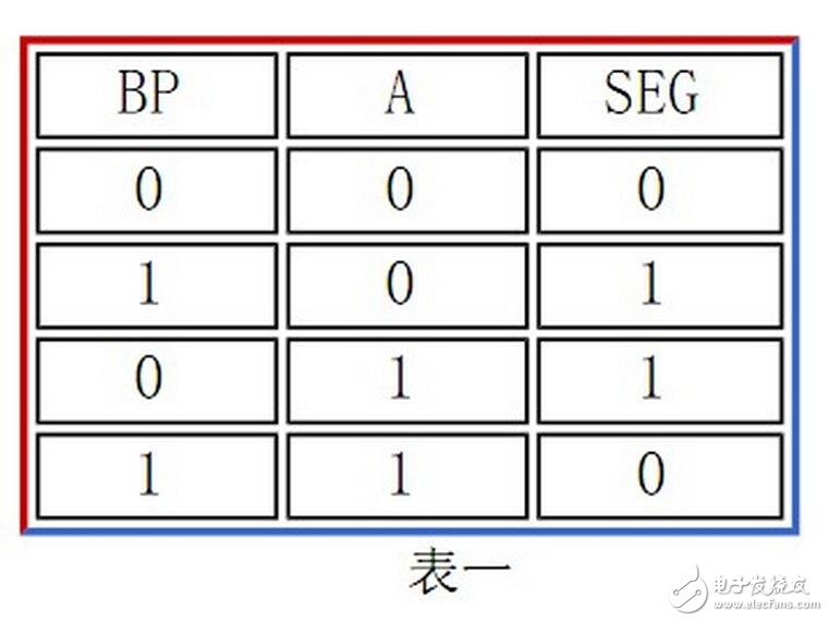
1. Static Drive Method The static drive method is the most basic method to obtain the best display quality. It is suitable for driving a pen-type liquid crystal display device. Table 1 shows the electrode structure of such a liquid crystal display device, and when the multi-digit numbers are combined, the back electrodes BP of the respective bits are connected together. The pulse signal of the oscillator is directly applied to the back electrode BP of the liquid crystal display device after being divided, and the pulse signal of the segment electrode is generated by logical exclusive OR synthesis of the display selection signal A and the timing pulse, when a certain display pixel is displayed. When selected, A=1, the pulse voltages of the two electrodes on the display pixel are out of phase by 180. A voltage pulse sequence of 2V is generated on the display pixel, so that the display pixel exhibits display characteristics; when a certain display pixel is non-display selected , A=0, the pulse voltages of the two electrodes on the display pixel have the same phase, and the synthesized voltage pulse is 0V on the display pixel, thereby achieving the effect of no display. This is the static drive method. In order to increase the contrast of the display, the voltage of the pulse can be appropriately adjusted.
When there are many pixels on the liquid crystal display device, such as a dot matrix liquid crystal display device, in order to save a huge hardware driving circuit, the fabrication and arrangement of the electrodes of the liquid crystal display device are processed, and a matrix type structure is implemented, that is, a level one is The back electrodes of the group display pixels are connected together, which is called a row electrode, and the segment electrodes of a vertical set of display pixels are connected together and called a column electrode. Each display pixel on a liquid crystal display is uniquely determined by the position of the column and row in which it is located. A raster scanning method similar to CRT is used correspondingly in the driving method. The dynamic driving method of the liquid crystal display is to cyclically apply a selection pulse to the row electrodes, and at the same time, all the column electrodes for displaying the data are given corresponding or non-selected driving pulses, thereby realizing the display function of all display pixels of a certain row. The scanning is performed line by line, and the cycle period is short, so that a stable image is displayed on the liquid crystal display. We call the scanning drive method of liquid crystal display a dynamic driving method.
Development status of LCD driver ICLCD drive types can be roughly divided into TN (TwistedNemaTIc), STN (Super-TwistedNemaTIc) (Note 1), and TFT (Thin-Film Transistors) and other three categories, of which TNLCD is mostly used in digital display, digital display, calculator, etc. The TFT is as small as the viewing window of the digital camera, and the LCD flat-panel TV as large as several tens of inches is used.
Therefore, the digital meter also needs an LCD driver IC. The large-size liquid crystal display also needs a driver IC. However, different types of LCDs and different size LCDs must be matched with different driver ICs. No LCD driver IC can conform to various types and The driving requirements of the size, so there must be a clearer and more specific definition of the scope when talking about the LCD driver IC, in order to fully explain and discuss.
Of course, the technology of LCD driver ICs such as TN and STN is quite mature, and the technological development and market growth have reached a certain level. Therefore, there has been little concern, and because of the maturity of technology, mainland IC design companies have gradually stepped in. In this field, this has also forced drive IC design operators in Japan, South Korea, and Taiwan to move toward higher-tech LCD driver ICs, from TN and STN to TFTs, from small to large.
Another driving force to accelerate the rise of Taiwan's driver ICs is from LCD panel makers. Since Taiwan has become a major assembly and manufacturing center for LCD panels in the world, if LCD driver ICs continue to rely on imports, it will be difficult to grasp the manufacturing cost and manufacturing time. Therefore, domestic panel makers are also active in the localization of LCD driver ICs. For example, Chimei Electronics (CHIMEI) turned to invest in Himax, and the LCD driver IC was developed by Qijing Optoelectronics to supply Chimei Electronics.
The LCD driver IC must first receive the picture signal from the LCD control IC before it can be driven by the digital to analog program, and the receiving input interface is still evolving.
At present, the most common interface is RSDS (ReducedSwingDifferenTIalSignaling), which is an interface defined by National Semiconductor (NS) for LVDS (Low-Voltage Differential Signaling) interface. The advantages are low electromagnetic interference (EMI), low power consumption, and as much transmission efficiency and picture resolution as possible. RSDS was originally NS's own technology, but it was later used. Most of today's timing controller chips and source driver chips implement RSDS interfaces. In addition, some people support the most traditional TTL (Transistor-TransistorLogic) interface.
After RSDS, NS proposed a new interface called PPDS (PointtoPoint Differential Signaling). The advantage of the new interface is to support higher picture resolution, higher transmission (operation) frequency, and also reduce the number of transmission lines. Not only can EMI be suppressed, but also save board layout area and cost. There is also a mini LVDS called mini-LVDS, which is also a new technology proposal in response to the trend of high size. The mini-LVDS also contributes to the reduction of the number of transmission lines. The mini-LVDS may also implement a point-to-point approach in the future. This will be called PPmL (PointtoPointmini-LVDS).
Common LCD driver IC1. Character LCD driver control IC
Characters such as 8×1, 8×2, 16×1, 16×2, 16×4, 20×2, 20×4, 40×4, etc., which are commonly used in the market, basically use KS0066 as the LCD driver. Controller
Second, the graphic dot matrix LCD driver control IC
1, the number of dots 122 × 32
2, the number of dots is 128×64
(1) ST7920/ST7921, support serial or parallel data operation mode, built-in Chinese kanji library
(2) KS0108, only supports parallel data operation mode, this is also the most common 12864 dot matrix liquid crystal drive control IC
(3) ST7565P, support serial or parallel data operation mode
(4) S6B0724, support serial or parallel data operation mode
(5) T6963C, only supports parallel data operation mode
3, other dot matrix numbers such as 192 × 64, 240 × 64, 320 × 64, 240 × 128 are generally using T6963c drive control chip
4, the number of lattice array 320 × 240, the general use of RA8835 drive control IC
LCD driver IC expansion functionThe LCD driver IC can use its drive control method to improve the liquid crystal image quality. Since the display of the conventional CRT (cathode ray tube, commonly known as the image tube) is to use the electron beam to strike the fluorescent substance, the luminescence effect of the fluorescent material begins to fade after the beam shifts. The relative LCD display is continuously retained, so the dynamic display effect of the LCD is not as good as that of the conventional CRT. In order to achieve the display characteristics close to the CRT, the LCD driver IC changes the driving mode, and also implements an intermittent pulse mode similar to the electron beam ( ImpulseType) to drive to improve dynamic image quality.
In addition, the LCD has a problem of slow residual liquid crystal response (Note 4). In order to reduce the effect of image sticking on image quality, the LCD driver IC also provides the drive control function of "black insertion, full black image insertion", that is, Before replacing it with the next screen, it will stop the driving of the entire LCD screen, so that the liquid crystal will appear black, and then change to the next screen. Of course, the time of this black screen is very short, only ten milliseconds, but it has elimination. The effect of afterimage. In order to implement the black insertion mechanism, the timing controllers that work in conjunction with the TFTLCD driver chip must also work together.
It should be noted that the LCD driver IC performs black insertion control, mainly using CCFL backlight. Today, many LCD TVs and liquid crystal displays have begun to adopt LED backlights. Because LEDs are light and extinguished, the response speed is extremely fast, unlike The CCFL is lighted and extinguished slowly. Therefore, the LED backlight can also be used to extinguish all the backlight LEDs in a short time to achieve the black insertion effect. At this time, the LCD driver IC is not required to perform black insertion.
Incidentally, if the black insertion is realized by means of software or image data transmission, the bandwidth consumption of the video transmission will be increased, and in order to avoid this consumption, it must be directly in the TFT LCD driver chip. The built-in black control function, the designer of the TFTLCD driver chip also increases the control pin (or: pin) of the chip. For example, the signal of BWSEL (BlackWhiteSelect) is added, and this pin is input into Hi. The (High) signal can be used to black-plug the TFTLCD.
Of course, there are not only one way to improve the afterimages or afterimages, but also the idea of ​​trying to solve them from other levels. For example, some developers have developed OCB high-speed liquid crystal materials to make the liquid crystal twisting operation faster, or some people believe that changing the operating dimension of liquid crystal can also accelerate the angular change of twisting. This is called vertical twisting, although vertical twisting can achieve faster. Torsion, but also because the reduction of the twist angle makes the liquid-shielding ability of the liquid crystal deteriorate. The result is probably that the liquid crystal transition speed is faster, but the blackness is also worse when it is black, because the liquid crystal is twisted to the extreme, There is still light that penetrates from the backlight to the front end.
Twinkle System Technology Co Ltd , https://www.pickingbylight.com