Compared with the wired remote control, the wireless remote control is not affected by the distance, completely eliminating the hidden troubles caused by the streamer type remote control device, and bringing more convenience to people's daily work and life. With the rapid development of digital processing technology, wireless digital communication technology is becoming more and more mature, its anti-interference ability is strong, and it is easy to perform various processing on digital signals, which makes the anti-interference performance of the wireless remote control system gradually improve, and the safety performance is greatly improved. The current wireless remote control field mainly includes ultrasonic remote control, infrared remote control and radio remote control. Compared with ultrasonic remote control and infrared remote control, radio remote control uses radio signals to propagate in the air. It is remotely controlled according to the frequency of radio waves. It can penetrate certain obstacles and travel far distances. Therefore, it becomes the first choice in the field of wireless remote control. The use of military, scientific research and daily work and life is becoming more widespread.
The radio remote control chip Si4010, wireless receiver chip Si4313 and C8051F920 developed by Silicon Laboratories are designed and fabricated with a frequency of 433.92 MHz. The radio remote control multiplexer system has simple structure, stable performance and convenient control. It is suitable for containing more controlled appliances. In the occasion, multi-channel multi-function control can be realized.
1 System working principle
The radio remote control multiplexer system is composed of two parts: a radio transmitting circuit and a radio receiving control circuit. The block diagram of the system is shown in Figure 1.
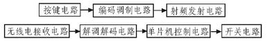
Figure 1 system composition block diagram
The working principle of the switch system is to first input the bit number of the required control switch circuit through the button circuit, and start the command code circuit, and the command code circuit generates the coded pulse signal with the address code information and the switch state information under the control of the internal circuit. The pulse signal modulates the carrier signal, and the modulated carrier signal is amplified and tuned by the RF transmitting circuit. After receiving the carrier modulation signal, the radio receiving circuit demodulates the carrier modulation signal by the demodulation decoding circuit to obtain a coded pulse signal, and then performs code address confirmation to confirm whether it is the address of the remote control switch system. If the received signal address code is the same as the local address code, the coded pulse signal is decoded and the data is output, and the corresponding switch circuit is controlled by the single chip circuit. Otherwise, the decoding is not performed, the microcontroller control circuit does not respond, and the switching circuit has no action.
2 Hardware introduction
The Si4010 RF Transmitter is a single-chip remote IC that requires a single external bypass capacitor, a printed circuit board, battery and a housing with buttons to form a complete radio remote control. The patented, highly reliable crystalless oscillator architecture eliminates the need for an external clock source and is immune to shock and vibration. Its carrier frequency accuracy is ±150 ppm over the commercial temperature range and ±250 ppm over the industrial temperature range. It is twice as accurate as conventional (SAW) transmitters and requires no external crystal oscillations. Device. With automatic antenna tuning, this function maximizes the transmission distance and provides stable output power, effectively reducing the adverse effects on the remote control. Includes an embedded compatible 8051 microcontroller with 1 4kB of RAM, 1 8kB of one-time programming (OTP) non-volatile memory, 1 128-bit EEPROM, and library function 12 kB ROM, digital peripheral functions on the microcontroller include touch-wake GPIO, a patented 20-bit EEPROM providing 1 million read and write lifetimes, 1 LED driver, 1 sleep timer, 1 A debugger and a high-speed 128-bit Advanced Encryption Standard (AES) accelerator that provides a secure unidirectional link. Operating over a wide range of 1.8 to 3.6 V, the Si4010 offers ultra-low current consumption (less than 10nA standby current and less than 20 mA peak current) and low-power touch wake-up mode. Support FSK, OOK modulation mode, support PCB loop antenna, working frequency band is 27 ~ 960 MHz, the chip also contains LDO, temperature sensor and low voltage detection alarm.
3 system hardware circuit design
3.1 Radio transmission system
The radio transmission system is mainly composed of a button circuit, a code modulation circuit, and a radio transmission circuit. The circuit schematic of the radio transmission system is shown in Figure 2.
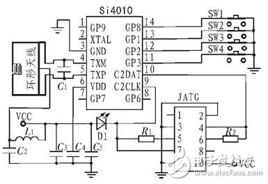
Figure 2 Schematic diagram of the transmission system circuit
The radio transmission system is designed with the Si4010 as the core. The four input and output ports of the Si4010 are directly connected to the buttons, and the internal circuit can directly collect the button status information. The signal differential outputs TXM and TXP of the Si4010 are respectively connected to the two ends of the loop antenna, and the loop antenna is directly printed on the PCB board, which reduces the volume of the transmitting system. Programming with the C2 interface, the C2DATA and C2CLK ports of the Si4010 are connected to the four ports of the JTAG interface. C3, C4, and C5 form a power supply filter circuit. The LED provides a button action indication. When a button is pressed, the light emitting diode is illuminated, no button is pressed, and the light emitting diode is off. The main function of the radio transmission system is to collect the state information of the button circuit under the control of the internal MCU of the Si4010, realize data encryption and encoding, and then perform FSK modulation. The modulated signal is amplified and tuned and transmitted by the loop antenna.
MLF advise many types of USB chargers , USB Power Adapters, USB network adpaters . 2.0 Usb Adapters as well as 3.0 USB ac adapters .and also 3.1 USB type. USB power adpater widly use in various industry.Let us match a high quality Usb Power Adapter for your device !
The main type is single USB Adapter , but also dual USB and mutiple USB port type also .can charge the two or more devices at one time. Please don't hesitate to contact if you want to know more details about the USB adapters!
USB Adapter
Usb Power Adapter,Usb 2.0 Adapter,Usb Power Supply,Usb Network Adapter
Meile Group Limited , https://www.hkmeile.com