Emergency lighting is a very important lighting device. It automatically charges the backup battery during normal power supply, automatically switches battery power after power failure, provides emergency lighting function, and is crowded in high-rise buildings, teaching buildings, shopping malls and entertainment venues. The place is widely used. Because it involves the safety evacuation of personnel in the building fire, fire emergency lighting and direction instructions, it plays a very important role in fire rescue, even known as the "light of life." LED is used as emergency light for emergency lighting. It has long life, low energy consumption, high color rendering, easy maintenance, small size, fast lighting speed, no stroboscopic light, and luminous efficiency is much higher than traditional light source, no harmful metal mercury. It is very environmentally friendly and has become a mainstream product. The design of LED emergency lighting is based on the premise of the national standard of fire emergency lighting (GB17945-2000), mainly from the realization of functions, main technical indicators, emergency lighting circuit design, normal lighting and charging control circuit design and automatic emergency Comprehensive design of conversion circuit design and other aspects.
1 Main functions of emergency lighting
The main functions of LED emergency lighting are as follows:
(1) Automatic switching function. When the power failure occurs, the built-in control circuit automatically switches the power supply within 5 seconds (within 0.25s in the high-risk area) and enters the emergency state. When the utility power resumes power supply, it automatically switches back to the charging state.
(2) Constant current charging function. When charging, the red and green indicators are on. When full, the red indicator light is off. At this time, the trickle charge state is turned; the green indicator light shows the main power state, and the mains power is normally turned on.
(3) Fault detection function. If the battery fuse is broken or the contact is poor, or the internal control circuit is abnormal, the built-in self-test circuit will automatically light up the yellow indicator.
(4) Over-discharge protection function. When the battery voltage is discharged to 80% of the rated voltage, the electronic switch immediately cuts off the discharge circuit to ensure the long life of the battery.
(5) Test button function. Under the condition that the main power is normally supplied, pressing the test button is equivalent to cutting off the external power supply for simulating the power failure state test. The emergency light can be turned off by pressing the button under the condition of main power failure.
2 Main technical indicators of emergency lighting:
According to the national standard (GB17945-2000), the main technical indicators that LED emergency lighting should reach.
(1) The emergency working time of the fire emergency luminaire shall be not less than 90min, and not less than the nominal emergency working time of the luminaire itself.
(2) Fire emergency luminaries shall be provided with main power, charging and fault status indicators. The main power state is green, the charging state is red, and the fault state is yellow. Centralized power-type fire emergency luminaries shall be provided with main power and emergency power status indicators, the main power status is green, and the emergency status is red. The fire emergency luminaire that shares the power supply line between the main power and the emergency power supply can use only the red indicator light.
(3) Fire emergency lighting should have over-charge protection and short circuit protection of charging circuit. The charging time of the fire emergency light should be no more than 24h, and the maximum continuous overcharge current should not exceed 0.05C5A (1C means battery capacity current, 0.05C is 0.05 times battery capacity current; C5 means 5 hours capacity discharge time). The maximum charging current of a centralized power-type fire emergency luminaire when using a maintenance-free lead-acid battery should not exceed 0.4 C20A.
(4) Fire emergency luminaires should have over-discharge protection. The battery discharge termination voltage should not be less than 80% of the rated voltage. After the discharge is terminated, the fire emergency light should not be restarted even if the battery voltage is restored without recharging, and the static bleeder current should be no more than 10-5 C5A. . The maximum discharge current of a centralized power-type fire emergency luminaire when using a maintenance-free lead-acid battery should not exceed 0.6 C20A. The battery discharge termination voltage should not be less than 90% of the rated voltage of the battery, and the static bleeder current should be no more than 10-5 C20A.
(5) The fire emergency luminaire should not be transferred to the emergency state within the range of 187~242V.
(6) The main electric voltage when the fire emergency luminaire is transferred from the main electric state to the emergency state shall be in the range of 132 to 187V. The mains voltage when returning from the emergency state to the main power state shall be not less than 187V.
(7) The insulation resistance between the main power input terminal and the casing of the fire emergency luminaire shall be not less than 50 MΩ, and the insulation resistance between the external live terminal and the casing with insulation requirements shall be not less than 20 MΩ.
(8) The main power input end of the fire emergency luminaire and the casing shall withstand a frequency of 50 Hz ± 1%, a voltage of 1500 V ± 10%, and a test of 60 s ± 5 s. The external live terminal of the fire emergency luminaire (rated voltage ≤ 50VDC) and the housing shall withstand a frequency of 50 Hz ± 1%, a voltage of 500V ± 10%, and a test lasting 60s ± 5s. During the test, the fire emergency luminaire shall not have surface arcing and breakdown. After the test, the fire emergency luminaire shall be able to work normally.
3 LED volt-ampere characteristics and power requirements:
According to the color of the light, the LED can be divided into blue light (InGaN) 470nm, green light Green (GaP: N) 550 nm, yellow light (GaP: N - N) 587 nm, red light Red (InGaAlP) 617nm, super Red-light Super-Red (InGaAlP) 630nm, white LED and other products. Due to the differences in their inherent characteristics, different power supplies need to be designed for their applications.
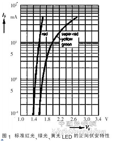
3.1 Volt-ampere characteristics of standard red, green and yellow LEDs For a standard red, green and yellow LED with a diameter of 5 mm, the curve of forward voltage (VF) and forward current (IF) is shown in the figure. 1 is shown. As can be seen from Figure 1, the standard red, green, and yellow LEDs have a forward voltage of 1.4 to 2.6V, and the forward voltage drop increases as the forward current increases. When the forward current is less than 10 mA, the forward conduction voltage changes only a few hundred millivolts.
The easiest way to use an LED is to apply a voltage source to a loop that is connected in series with the LED. As long as the operating voltage remains constant, the LED can emit a constant intensity of light (although the intensity decreases as the ambient temperature increases) By changing the resistance of the series resistor, the light intensity can be adjusted to the required intensity. For example, with a 5V power supply, a green LED with a forward operating current of 10mA should have a constant operating voltage of 2V, then the series resistor is R=(5 -VF)/10mA = 300Ω.