How to solder VGA head
The order of the solder joints on the back of the male

First, the definition of each pin of 15-pin VGA:
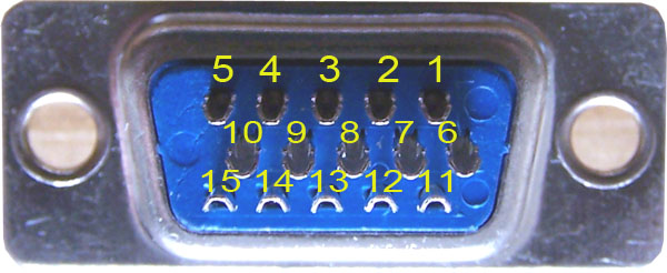
According to the standard of VGA connector (15HD), the definition of each pin is as follows: (PIN means "foot")
1PIN - Red - "red" analog signal
2PIN - Green - the "green" of the analog signal
3PIN - Blue - the "blue" of the analog signal
4PIN - ID Bit,
5PIN - N/C,
6PIN - R.GND - the "red" ground of the analog signal
7PIN - G.GND - the "green" ground of the analog signal
8PIN - B.GND - "Blue" ground of the analog signal
9PIN - No.Pin, (alternate)
10PIN - GND - ground of several sub-signals
11PIN - ID Bit - control or address code between the screen and the host
12PIN - ID Bit - Control or address code between the screen and the host (for multiple displays of one host)
13PIN - H Sync - digital horizontal line signal
14PIN - V Sync - digital vertical line signal
15PIN - N / C - ground

Second, the standard 15-pin VGA head welding method:
The pins of the standard 15-pin VGA head are shown below (3+4 line type, 3 means 3 coaxial red, green, blue, 4 means 4 black, brown, yellow, white lines) VGA feet usually follow the inverted trapezoid From the top to the bottom, from left to right are 1-5 feet, 6-10 feet, 11-15 feet; (note that the D15 connector must use a metal casing) as shown below:
15 pins we usually only need to solder 11 pins, as follows: (4, 5, 9, 12 feet are not welded)
Red line - "1" foot - "red" of the analog signal;
Green line - "2" foot - "green" of the analog signal;
Blue line - "3" foot - "blue" of analog signal;
Red line shielded wire - "6" pin - "red" grounded shielded line of analog signal;
Green line shielded wire - "7" foot - "green" ground shielded line of analog signal;
Blue line outer shield line - "8" foot - "blue" ground shield line of analog signal;
Black line - "10" foot - the ground of the number of sub-signals;
Brown line - "11" foot - control or address code between the screen and the host;
Yellow line - "13" foot - digital horizontal "line" sync signal;
White line - "14" foot - vertical "field" sync signal of the number of sub-signals;
VGA off-line shielded cable - "15" pin - VGA socket housing is crimped to ground.
In actual engineering, there are often errors in the connection of the ground wire. If some feet (such as 4, 5, 9, 15 etc.) are connected to the ground line, there is no problem in the big screen; but like 10 If the foot is not grounded, there will be a problem with the ground wire not working. Some devices have all unused pins grounded. Although not standard, they are practical, but they can be problematic if the corresponding control bits are used.

Third, VGA pin welding only 7 wire welding method: (such as the use of 8-core welding in the network cable)
The first, 1, 2, and 3 feet respectively use the three lines (1-orange, 2-green, 3-blue) in the network cable to record the color correspondence on both sides;
Second, 5~10 feet are welded together for common ground; use one of the 8 color lines (here we remember the "orange-white" color line), remember that the lines with both colors are used at both ends. , 6, 7, 8 pin welding together to the public ground;
A line in the third and eleventh network cable (defined here as a brown line, 11-brown)
The fourth and 13 feet are connected to a certain color line in the network cable (here defined by green and white lines, 13-green);
The fifth and 14 feet are connected to a certain color line in the network cable (here defined by green and white lines, 14-blue and white);
The sixth and 15-pin VGA socket housings are crimped to ground. (The green and white lines are defined here, 15-brown)
Pin 15 should actually be used as a ground wire with 5-10 soldering, which is actually soldering 7 pins.
If the special VGA cable is used to simply solder 7 pins, the welding method is: the 5~10 pins at both ends of D15 are welded together to make a common ground; the red, green and blue shield wires are twisted together to be connected to the public ground; 2, 3 feet are connected to the red, green and blue core wires; 13 is connected to the yellow wire; 14 is connected to the white wire; the outer shield is crimped to the D15 plug end shell, the brown and black wires are not connected, but should be cut to Prevents other lines from being connected in series.
Fourth, VGA cable deployment and construction issues:
1. Cable selection: It is best to purchase special VGA cable in general engineering and home. The price level is not uniform. The average price is moderate: 8-10 yuan/meter, less than 8 yuan/meter may not be good. , above 13 yuan / meter should be considered good quality. If you really have no conditions to buy, then use something else, such as the use of network cable, the best distance between the network cable should not exceed 10-15 meters, about 5 meters can be, and the long image effect is not good.
7 lines of VGA cable: There are 7 lines in the dedicated VGA cable, and the outer shield layer is used as one line. Among the 7 lines, there are one red, blue and green. Note that each of the three is A thin coaxial line with a shield, so these three lines are actually six pins, one for each of black, brown, yellow, and white. So don't be surprised when you buy the line. There are only 7 lines instead of 11 or 15 inside. If you read this, you don't know that it is a spoon.
2, wiring distance: the distance required by the single-segment VGA cable standard is not more than 15 meters, but our usual application is not so strict, because our image requirements are not so high, under normal circumstances, 40 meters can also be used . Add VGA amplifiers when you are over 40 meters or if the images are not working well. It is best not to use more than 15 meters of cable or other unshielded cable. Usually we want to put images on one computer on multiple monitors or computers, then you go to Computer City to buy a VGA splitter, the price is about 60 yuan.
3, interference problem: the image is not clear or there is interference is probably the signal is not good or there is interference, the wiring should not be with the speaker speaker cable, the interference of that line is very large. The welding head is to be welded, do not engage in the grass. If the head is close to the power socket or the power strip, it is best to take a metal box to shield the joint or the starting point.
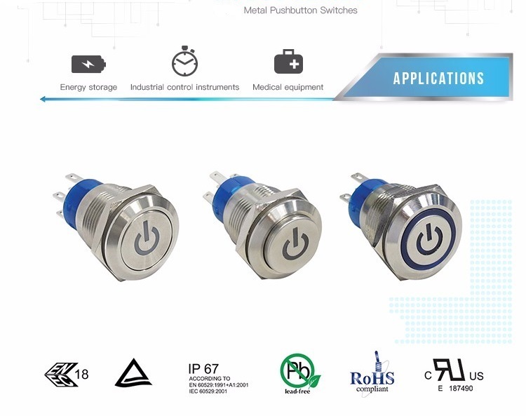
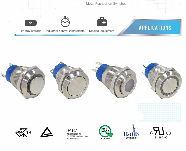
19MM Metal Switches , also known as Metal Push Button Switch in harsh working environment. The most competitive advantage of this Metal Switches is that it is high mechanical life, in which momentary could reach 1,000,000 cycles and self lock is 500,000 cycles. Stainless steel is resistant to damage IK10, it is very hard and reliable. Therefore, this series of metal switch is widely used in automobiles, ships, medical and large mechanical equipment.
In order to ensure the trust of our customers, this series Push On Push Off Switch has passed UL testing and certification, IP67 dust-proof and waterproof certification, TUV, European and American environmental protection RoHS and lead-free environmental protection certification .

Our 19mm Waterproof Push Button Switch have a variety of materials, including stainless, brass with nickel plated, brass with chrome plated, AI alloy with black anodized. This serious Push On Push Off Switch could offer different LED light, including white, red, yellow, green. Customer can select power logo indicator when controlling the power supply, customers could choose the double color indicator light when Switching different function.
Furthermore, all the LED indicate light are provided by well-known LED lamp manufacturers, guarantying the long-term use of LED lights and high-life mechanical life

19MM Metal Switches
19MM Metal Switches, Metal Push Button Switch, Push On Push Off Switch, Waterproof Push Button Switch
YESWITCH ELECTRONICS CO., LTD. , http://www.yeswitches.com