Abstract: A software and hardware design scheme of intelligent voice fee display based on voice chip ISDl760 is presented. The structure, function and usage of voice chip ISDl760 are also introduced. The system can be widely used in highway toll collection systems and weighing systems to further improve the level of charge management and enhance the transparency of charges.
Keywords: intelligent voice; fee display; ISD; SPI;
This article refers to the address: http://
0 Introduction The voice fee display is an electromechanical device used to display information such as models and charges for ordinary and highway toll lanes to payable vehicles and personnel. It is usually installed at the side of the entrance and exit of the toll lane. It can display the model, amount, balance and Chinese character information, and has functions such as traffic instructions and voice prompts. This paper takes SST89V58 single-chip microcomputer and voice chip ISDl760 as the core, and gives a design method of voice fee display.
1 Introduction to voice chip ISDl760 ISDl760 is one of Winbond's new single-chip high-quality voice recording and playback circuit ISDl700 series chips. This chip can be used to replace the already discontinued ISD2560 chip. The user can use the oscillating resistor to calculate the sampling frequency of the chip, which determines the recording and playback time of the chip (40~120 s) and the recording and playback quality (4~12kHz). Compared with the past ISD2560 chip, ISDl760 integrates the function of recording and playback, and adds some more user-friendly prompting functions and precise operation of the storage space, and the sound quality has also been significantly improved.
The ISDl760 chip offers several new features including a built-in multi-information management system, new information prompts (vAlert), dual-operation modes (stand-alone mode and SPI mode), and customizable information operation indicator sound effects. The chip contains a full range of integrated system functions such as automatic gain control, microphone preamplifier, speaker driver circuit, oscillator and memory. In addition, the chip also has a patented analog processing storage method, and the recording and playback quality is excellent, the background noise is small, the voice content is stored for a long time and is not easy to be lost. It is very suitable for voice broadcasts on highway toll stations and buses.
The ISDl760 has two modes of operation, independent mode and SPI mode. The system adopts the SPI working mode, in which the single chip microcomputer is the host and the ISDl760 is used as the slave. The main control MCU mainly communicates with the ISDl760 through the four-wire (SCLK, MOSI, MISO, /SS) SPI protocol, and almost all operations can be completed by the SPI protocol.
2 Voice fee display hardware design A voice fee display system can be composed of main control module, storage module, voice module, power amplifier module, serial communication module, drive module and display module. The main control system block diagram is shown in Figure 1. Show. The communication command for the fee display is derived from the lane control computer of the toll system. The computer can send the final data obtained by mathematical calculation formulas such as vehicle type, axle load, driving mileage and billing standard to the RS-232 communication chip of the fee display through the serial port, and then input the data by the RS-232 communication chip. The microcontroller processes it. The data processed by the MCU can be divided into two outputs, one of which is output to the decoding and driving chip for driving the display of the digital tube; the other is output to the voice chip for synchronous voice quotation.
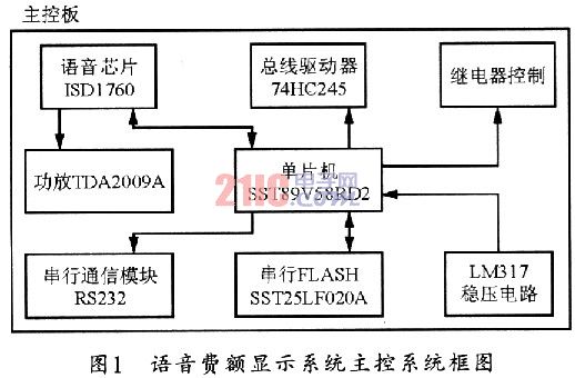
Since the system uses the 2MB serial FLASH chip SST25LF020A to store the font contents, the SST89V58 MCU with SPI interface can be used as the main control chip, and the analog SPI method is used for serial communication with the ISDl760.
The four pins with IO function on the MCU can be connected to SCLK, MOSI, MISO on ISDl760 respectively; the ROSC terminal of ISD760 can be grounded with an 80 kΩ resistor, that is, the sampling frequency is set to 8 kHz. The maximum recording and playback time under the sampling rate is 60s; the power amplification circuit composed of SP+ and SP-end external TDA2009A can realize the volume control of the broadcast voice. The TDA2009A is a dual audio power amplifier with an overheat protection circuit and few external components for easy installation.
The content of the voice broadcast of the fee display mainly includes the broadcast greeting, the model, the amount of the charge, the weight of the car, the alarm sound, and the like. The system uses the ISDl700 voice programming copy machine to record the recorded voice segments into the voice chip. In addition, the voice program can also be used to easily read the start and end addresses of each piece of voice information, and can copy multiple pieces of chip voice information.
In the process of voice recording, the first problem to be aware of is to check the computer sound card driver before burning the voice. It should be guaranteed to have the latest driver. It is best to set the speaker configuration in the sound card sound output setting to the earphone and output volume setting. In the state of two-thirds; the second is to burn the voice, the computer in addition to running the program to burn the voice, other applications (such as anti-virus software, etc.) to close, to ensure that no noise mixed in; finally, in the burning After the voice chip is finished, you can play it back and forth. If you are not satisfied with the sound quality, you can use the audio editing software such as Goldwave or Adobe Audition to edit the voice file, which has achieved satisfactory results.
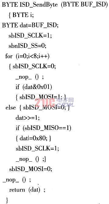
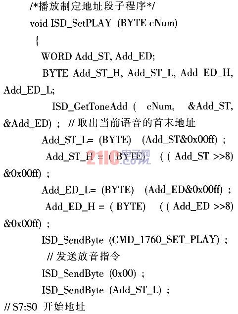
3 Software Program Design The system software of the voice fee display is to process the serial communication data sent by the toll computer in the toll booth, complete the corresponding display function and perform voice announcement. The voice processing program mainly determines whether it is necessary to broadcast the voice information, and finds the storage address of the corresponding voice information, and broadcasts the segment voice. The system program flow chart is shown in Figure 2. The following is a subroutine that simulates the SPI send data subroutine and plays the specified address segment:

/* Simulated SPI send data subroutine*/
4 Conclusion This system uses the IO port of the microcontroller to simulate the SPI interface to control the ISDl760, which is suitable for most microcontrollers to communicate with the ISDl760. In practical applications, analog components (AGC resistors and capacitors, coupling capacitors, etc.) should be as close as possible to the ISD device. The pins of the components should be short. The analog and digital power pins should be connected to the power supply terminal, and the two power supplies should be connected. The port adds a high frequency decoupling capacitor, and its equivalent series resistance is small, and the power supply itself must not be noisy.
Wireless Led Smart Control Box with 6*3.5A+1*8A output socket. 2. 8A output socket can work with longer and high power light and ribbons. It`s Wireless receiver, 2.4G/BLE/Zigbee are available. The Led Smart Control Box is dimmable, Soft on/ off with memory function.
Advantages of Wireless LED Smart Control Box
With 6*3.5A+1*8A output socket
8A output socket can work with longer and high power light and ribbons
Wireless receiver, 2.4G/BLE/Zigbee are available
Dimmable
Soft on/ off with memory function

Wireless LED Smart Control Box
Wireless Led Smart Control Box,Wireless Smart Control System,Control Box For Led Light,Wireless Smart Control Box
Shenzhen Jedver Smart Lighting Co., Ltd. , http://www.jederwell.com